-1.png)

Commercial PBT families can combine dimensional stability, electrical insulation, reinforcement, and flame-retardant options. Those family-level advantages do not establish compliance for a finished electrical part.

The qualifying evidence is narrower: exact producer and grade, exact color, recognized thickness range, applicable UL 94 classification, comparative tracking index (CTI), glow-wire properties when required, and the conditions of the end-product standard. PBT injection molding then has to preserve material identity and produce the wall thickness and condition that the design assumed.
UL 94 Is Thickness-Specific and Still Preliminary
As of August 25, 2026, UL 94 is in its seventh edition and was most recently revised on July 2, 2026. UL describes it as a method for assessing the flammability of plastic materials in devices and appliances using small-scale tests. The standard also states that the results provide only a preliminary indication of suitability; final acceptance depends on use in complete equipment under the applicable end-product standard. [1]
Thickness is part of the result. UL's Plastics Recognition guidance explains that a material recognition includes a minimum thickness or thickness range, the colors tested, and the rating achieved. [2] Therefore, a drawing note such as "PBT, UL 94 V-0" is incomplete. The released specification should identify:
-
resin producer, exact commercial grade, and approved equivalents;
-
color designation, including whether all colors or only named colors are covered;
-
nominal and minimum local wall thickness at the relevant insulating or fire-exposure region;
-
required UL 94 classification at that thickness;
-
the current UL Yellow Card or certification record;
-
recognition conditions for regrind, colorant, or additives;
-
the end-product standard and any component condition of acceptability.
If the design is thinned, a new color is introduced, or a local knit line or tolerance reduces the actual section, re-check the recognition. A V-0 classification at a thicker test specimen cannot be silently transferred to a thinner wall. Conversely, the test result is not a prediction of flame behavior under every end-use geometry, ignition source, ventilation condition, or adjacent material. [1]
CTI Informs Insulation Design; It Does Not Set Creepage Alone
IEC 60112:2025, corrected in February 2026, measures comparative tracking index and proof tracking index on solid insulating materials exposed to an electrolyte contamination at voltages up to 600 V AC. IEC states that composition and surface condition influence the result and that CTI is intended for material comparison and basic characterization. It explicitly warns that CTI is not directly suitable for determining safe creepage distances. [3]
That boundary prevents a common specification error. A higher CTI can support a more favorable material-group input within an applicable insulation-coordination or product standard, but the allowable creepage distance also depends on factors such as working voltage, pollution degree, insulation type, surface geometry, and the governing product rules. IEC 60664-1 addresses clearances, creepage distances, and solid insulation for equipment within its stated low-voltage scope; it does not reduce the design to a single CTI number. [4]
For a terminal housing or connector, document CTI with the minimum creepage path on the toleranced part, working voltage and overvoltage assumptions, pollution degree, insulation category, product standard, and the grade/color/thickness represented by the material record.
Mold flash, contamination, ribs, grooves, ejector features, parting lines, and assembly position can change the physical path. A high material CTI does not excuse a nonconforming molded creepage geometry.
GWFI and GWIT Answer Different Glow-Wire Questions
The IEC glow-wire apparatus simulates thermal stress from sources such as glowing elements or temporarily overloaded resistors. The current common test-method standard is IEC 60695-2-10:2026. [5] Whether a particular component must meet a glow-wire requirement, and which requirement applies, comes from the end-product standard and component use - it is not mandatory for every PBT electrical part.
Two material properties are often confused:
| Property | What the materials test establishes | What it does not establish |
|---|---|---|
| GWFI - glow-wire flammability index | Highest specified test temperature at which the specimen does not ignite, or flames extinguish within the stated time and dripping does not ignite the tissue indicator | Automatic acceptance of the finished product or a GWIT result |
| GWIT - glow-wire ignition temperature | A materials-screening temperature based on whether ignition persists beyond the method's threshold | Finished-part performance at every thickness, geometry, or installation condition |
IEC 60695-2-12:2021 covers GWFI and IEC 60695-2-13:2021 covers GWIT. Both describe their material tests as preselection methods whose use depends on subsequent end-product evaluation. [6][7] UL's recognition guidance likewise lists GWFI, GWIT, CTI, thickness, and color as separate properties or conditions rather than interchangeable claims. [2]
A useful electrical-material matrix has one row per exact grade and color, with separate columns for UL 94 class and thickness, CTI, GWFI and specimen thickness, GWIT and specimen thickness, source record, and required end-product clause. Empty cells should remain visibly unapproved rather than being inferred from a similar grade.
Separate Wet-Resin Processing Damage From Hydrolysis in Service
Moisture creates two related but distinct risks for PBT.
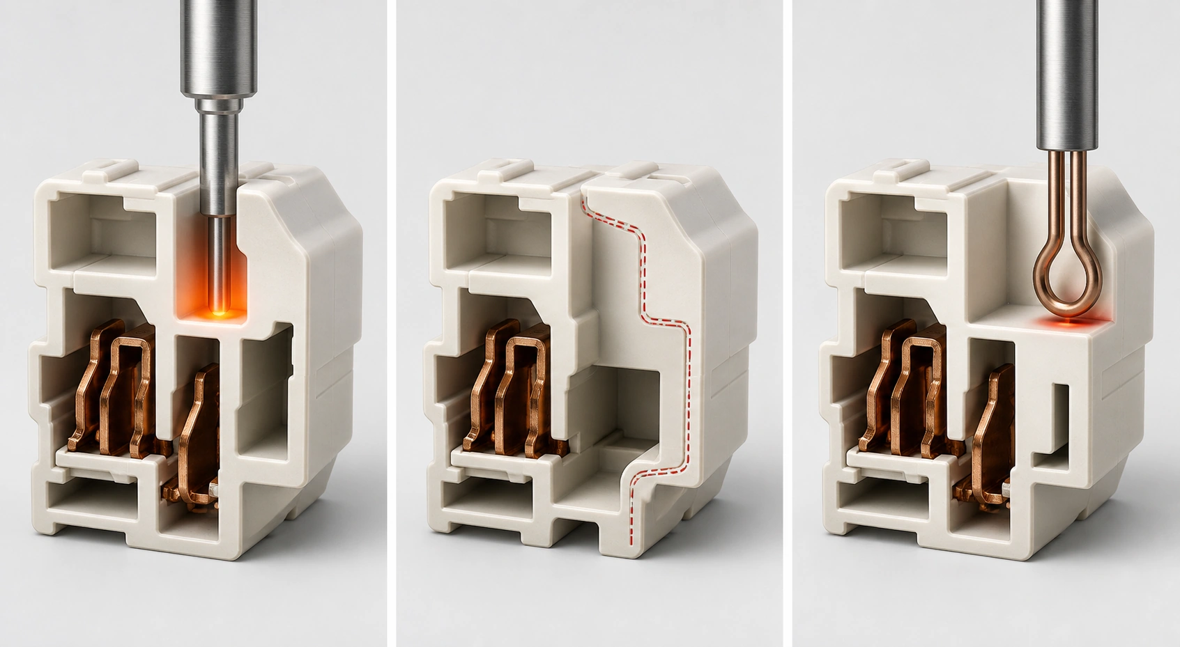
During molding, insufficiently dried PBT can undergo chain cleavage in the melt. BASF states that wet Ultradur can lose molecular weight, impact resistance, and elasticity even when the surface looks acceptable. For that product family, it gives a general moisture limit below 0.04% and four hours of drying at 80-120 degrees C, subject to grade data. [8]
During service, water or moisture, especially at elevated temperature, can also split chains and reduce properties. Hydrolysis-stabilized grades slow this degradation; service life still depends on temperature, humidity, stress, chemicals, and time. Defined hot/wet aging and retained-property data are the appropriate evidence. [8]
Do not turn BASF's family guidance into a universal PBT drying window. Celanese, for example, publishes different moisture and drying guidance for its Celanex product family and tells users to follow the selected grade's data. [9] The released molding instruction should name the validated dryer type, temperature, time or dew-point condition, maximum hopper residence, moisture test method and limit, and rules for material exposed during stops.
A molded part that passes incoming dimensional inspection has not thereby proved PBT hydrolysis service life. A service-life claim needs the exact grade and color, exposure temperature and humidity or immersion condition, mechanical/electrical endpoint, stress state, chemical environment, test duration, acceleration rationale, and end-product acceptance rule.
Compare PBT and PA66 by Grade and Environment
The question "PBT vs PA66 connector material" has no universal winner. Unmodified and reinforced PBT grades often offer low moisture uptake and relatively stable electrical and dimensional behavior across ambient humidity. BASF describes these traits for its Ultradur PBT portfolio. [8] Polyamide 66 can offer attractive toughness and thermal/mechanical performance in appropriate grades, but polyamides absorb moisture from their surroundings and their properties differ between dry and conditioned states. BASF publishes both dry and conditioned data for its Ultramid polyamide portfolio for this reason. [10]
The useful comparison is application-specific:
-
CTI, UL 94, GWFI, and GWIT for the exact grade, color, and thickness;
-
properties and dimensions in the actual conditioned environment and duty cycle;
-
retention, latch, impact, creep, weld-line, warpage, and assembly requirements;
-
availability, approved colors, and traceability.
Do not impose one continuous-use temperature or cost ranking on both polymer families. Those values are grade-, load-, test-, region-, and commercial-condition-specific.
Control Warpage Around Flow and Thermal Symmetry
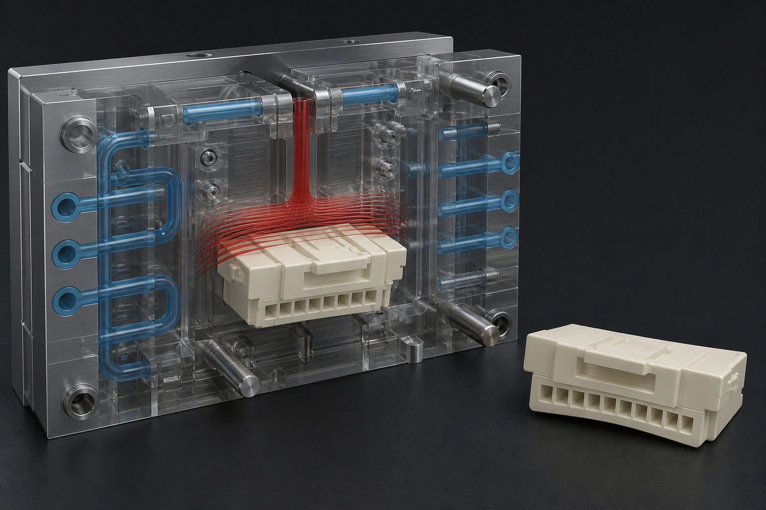
Glass reinforcement can reduce bulk shrinkage while increasing directional behavior. BASF explains that glass-fiber orientation creates different shrinkage parallel and transverse to flow and that wall thickness, gate position, part design, and processing affect warpage. [8] A long connector body may therefore bow or twist even when every individual wall is within its local thickness tolerance.
Review PBT injection molding DFM for:
-
wall transitions, heat sinks, and cooling symmetry;
-
gate position, weld lines, and fiber orientation at critical features;
-
minimum walls, flatness, pitch, and true position after stated conditioning.
Melt temperature, mold temperature, fill rate, and pack profile must follow the exact grade's recommended and validated window. A universal rule such as "reduce mold temperature by 10 degrees to remove bow" can change crystallization, surface, shrinkage, and pressure transfer in ways that shift rather than solve the failure.
Verify the Tool Thermal and Wear State
A controller setpoint is not the same as the steel temperature seen by the cavity. After the process reaches thermal equilibrium, measure actual A-side and B-side steel temperatures at named, repeatable points near the critical cavity regions. Record the point, method, time in cycle, and stabilized process state. Compare the two mold halves and local regions, but do not impose a universal allowable temperature difference: the acceptable map depends on the grade, geometry, flatness target, cooling design, and validated process. Celanese's PBT guidance emphasizes separate cavity/core temperature control and cooling close to thick sections rather than relying on one displayed setpoint. [9]
Verify every cooling circuit before changing the process to chase bow or pitch. The check should cover connection and flow direction, flow rate or an agreed hydraulic proxy, pressure drop, inlet/outlet temperature, leakage, blockage, and whether cavity and core circuits can be controlled as designed. Keep the as-tested circuit map with the T1 record so a later thermal imbalance can be distinguished from an original design issue.
The gate region also needs a material-specific wear plan. When the selected PBT grade contains glass or mineral reinforcement, or its additive package creates a documented wear or corrosion risk, identify the gate insert or forming steel, heat-treatment and hardness range, any surface treatment, the replaceable boundary, and the inspection baseline. Do not infer one universal steel grade or hardness from the polymer family; confirm the exact compound, gate geometry, expected life, finish, and repair strategy with the resin supplier and toolmaker. [8][9]
Regrind Permission Must Be Traceable
"No regrind for high-CTI parts" is not a universal materials rule, and "25% regrind is always safe" is equally indefensible. Reprocessing adds heat history and can introduce moisture, contamination, color drift, fiber damage, and material mixing. BASF advises checking viscosity because degradation can occur in each processing cycle. [8]
Celanese publishes general regrind guidance for its polyester family and notes that conformity for some UL-recognized grades is tied to specific regrind conditions. [9] This illustrates why the rule is recognition- and grade-specific. The project record should state the allowed percentage and source, number of passes, drying and segregation method, contamination control, lot traceability, property-verification plan, and the exact supplier and UL evidence authorizing the condition. If that evidence is absent, do not infer permission.
Build a Grade-Thickness-Requirement Handoff
Before tool release, place the material matrix, wall-thickness map, creepage paths, critical electrical features, approved color, drying control, and regrind rule in the DFM record. At T1, confirm the resin lot and certificate, actual minimum walls, flash or mismatch along insulation paths, dimensions by cavity, warpage after stated conditioning, and any component tests required by the qualification plan.
Our plastic injection molding service and electronics injection molding guide provide public scope and design context, while our inspection workflow lists DFM, incoming-material, in-process, and T1 dimensional checkpoints. For an electrical PBT part, use those checkpoints to attach the exact grade/color/thickness compliance matrix and project-specific tests. The public pages should not be interpreted as proof that every UL, CTI, glow-wire, or end-product test is performed in-house.
Frequently Asked Questions
Is UL 94 V-0 enough to specify PBT for an electrical housing?
No. Verify V-0 for the exact grade, color, and minimum relevant thickness, then apply the component conditions and end-product standard. CTI, glow-wire performance, temperature, mechanical life, and creepage remain separate requirements.
Does a higher CTI allow a shorter creepage distance?
It may affect the material-group input in an applicable design rule, but CTI alone does not determine safe creepage. Working voltage, pollution degree, insulation type, geometry, and the governing product standard must also be evaluated. [3][4]
Are GWFI and GWIT interchangeable?
No. GWFI evaluates flammability behavior under the materials test; GWIT evaluates an ignition threshold under a different materials test. Record each required property, test thickness, exact material, and end-product rule separately. [6][7]
Can a molded PBT part look good after moisture damage?
Yes. Supplier guidance warns that wet material can suffer molecular-weight and mechanical-property loss without an obvious surface defect. Control resin moisture before molding and validate hot/wet service exposure separately. [8]
Conclusion
Specifying PBT for electrical parts requires three separate evidence lines: UL 94 at the actual minimum wall and color, CTI within the applicable insulation design, and GWFI/GWIT when the end-product standard requires them. Add hot/wet life, dry-resin processing, regrind traceability, fiber-driven warpage, and T1 measurement. The defensible unit of approval is not "PBT" alone; it is an exact grade, color, thickness, condition, requirement, and source record.
Sources
[2] UL Solutions: Plastics Recognition Program Webinar Series
[5] IEC: IEC 60695-2-10:2026, Glow-Wire Apparatus and Common Test Procedure
[6] IEC: IEC 60695-2-12:2021, Glow-Wire Flammability Index Test Method for Materials
[7] IEC: IEC 60695-2-13:2021, Glow-Wire Ignition Temperature Test Method for Materials
[8] BASF: Ultradur PBT Product Brochure
[9] Celanese: Celanex PBT Processing and Troubleshooting Guide