-1.png)

The first molded parts are the first time the production material, gate, cavity pressure, cooling, geometry, and actual tool meet in one result. That makes a dimensionally perfect T1 desirable, but not a sound design assumption. Shrinkage data comes from controlled specimens; a real part contains changing wall thicknesses, flow directions, constraints, and pressure gradients. ASTM D955 explicitly warns that its standard-specimen data cannot predict absolute shrinkage in real parts with different flow paths and process conditions. [1]
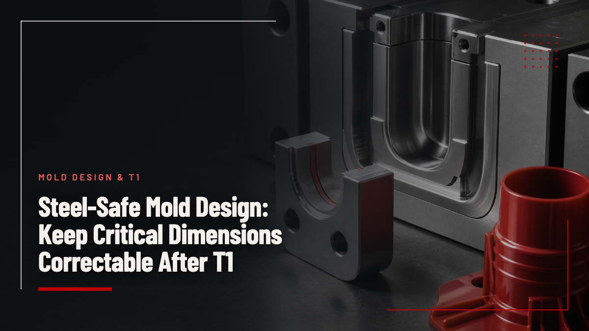
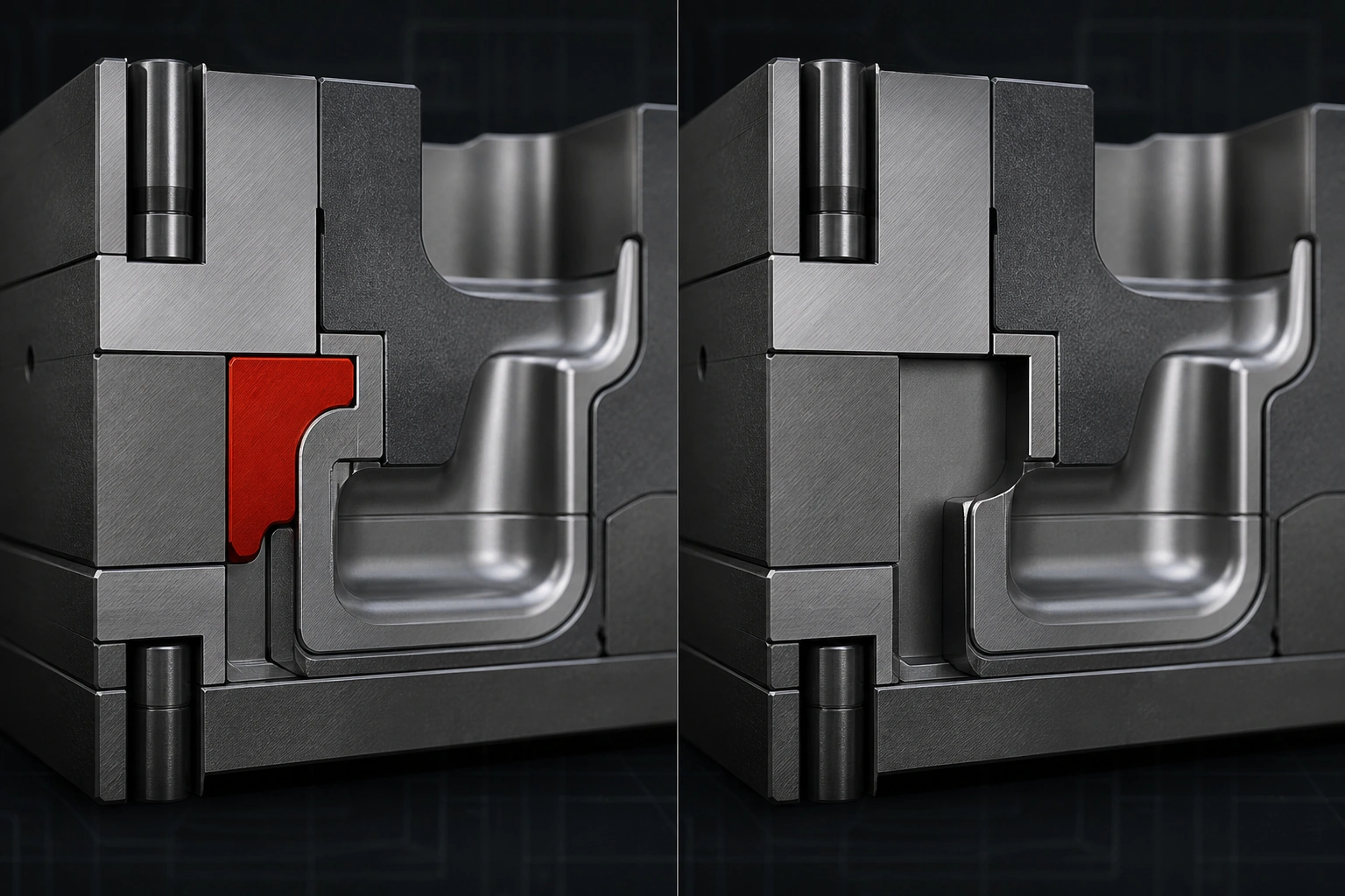
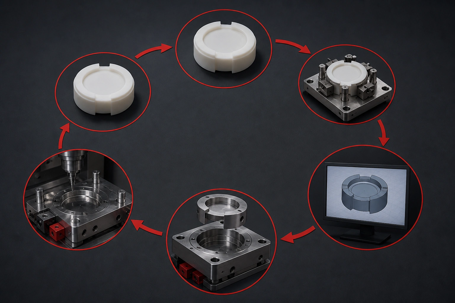
A steel safe mold design accepts that uncertainty without relaxing the part requirement. For selected critical features, it leaves the tool on the side from which the dimension can be corrected by removing steel after T1. The goal is not to make every dimension adjustable. It is to decide, before machining, which errors would otherwise force welding, a replaceable insert, or a new component.
Start With the Current Tolerance Framework, Not a Shop Rule
As of August 2026, ISO 20457:2026 is the current international standard for geometrical and dimensional tolerances and acceptance conditions for plastic molded parts; it replaced the 2018 edition. Its scope includes general tolerances, direct tolerances for functional needs, manufacturing effort, and acceptance conditions. It does not cover surface imperfections or joint lines. [2]
For U.S.-style product definition, ASME Y14.8-2022 covers drawing practices for castings, forgings, and molded parts, while ASME Y14.5 establishes the broader language of geometric dimensioning and tolerancing. [3] These standards answer a different question from steel-safe planning:
-
The product definition states what the finished part must satisfy.
-
The tolerance framework establishes how those requirements are communicated and accepted.
-
The steel-safe plan establishes how the tool can move toward those requirements after molded evidence is available.
Steel-safe stock is therefore not extra tolerance for the supplier. A feature that is intentionally conservative at T1 still needs a documented disposition and, after correction, must meet the agreed part definition.
The drawing review should identify the dimensions that actually control fit, sealing, alignment, motion, safety, or downstream assembly. Applying unusually tight direct tolerances to every modeled edge hides that priority and increases inspection and tooling risk without necessarily improving function. A more useful package applies an agreed general tolerance scheme where appropriate and reserves direct tolerances and steel-safe decisions for functional features.
Steel-Safe Means Preserving the Removal Direction
Material-producer tooling guides state the principle clearly. Solvay's Amodel PPA guide recommends cutting cores that form internal features oversize and mold features that form external dimensions smaller than expected, then sampling, measuring, and making final adjustments. Its Ixef PARA tooling bulletin reduces the logic to the governing fact: removing steel is easier than adding it. [4][5]
That principle becomes useful only when translated feature by feature:
| Part requirement | Typical mold-forming condition | Possible conservative T1 direction | Removal-based correction |
|---|---|---|---|
| External width or diameter | Enclosed by cavity steel | Molded feature slightly small | Enlarge the cavity by removing steel |
| Internal hole or pocket | Formed by a core | Molded feature slightly large | Reduce the core by removing steel |
| Rib or boss wall | Defined by two opposing steel surfaces | Depends on which surface may move without harming adjacent geometry | Remove steel only from the designated correction surface |
| Location between features | May involve one insert, two mold halves, or a slide | No safe universal sign | Assign datums, contributors, and correction component explicitly |
These are planning directions, not universal offsets. Draft, texture, shutoffs, concentric features, paired fits, and shared steel can make a cut improve one characteristic while degrading another. The correction plan should name the tool component and surface to be modified, not merely label the part dimension "steel safe."
Welding may be technically feasible for some tool steels and surface requirements, but it adds metallurgical, distortion, finishing, and timing questions. Replaceable inserts are often the better deliberate solution when a feature has two likely correction directions, is expected to wear, or may change with the product design. The important decision is made in the mold architecture, before a failed T1 makes the insert suddenly desirable.
Size the Strategy to Shrinkage Uncertainty, Not a Material Family Label
ISO 294-4 measures molding and post-molding shrinkage parallel and normal to melt flow. It also defines molding shrinkage as free shrinkage in a standardized specimen, not the restricted behavior of every production geometry. [6] ASTM D955 likewise identifies mold temperature, melt temperature, fill time, and packing as significant variables and limits its measurements to comparable standard specimens. [1]
Consequently, an allowance copied from a generic resin-family range is weak evidence. The review should record:
-
The exact resin producer, grade, reinforcement, color, and approved alternatives.
-
Supplier shrinkage data in each reported direction and the specimen or test method behind it.
-
Predicted flow and fiber orientation relative to each critical dimension.
-
Gate and packing paths, especially where pressure loss changes along a long feature.
-
Any post-molding condition—moisture conditioning, annealing, or assembly restraint—required before acceptance.
Filled materials do not simply need a "lower shrink factor." Fiber orientation can create different shrinkage along and across flow, so moving a gate can change the dimensional result even when the resin designation stays the same. The gate map and critical-dimension map should therefore be reviewed together.
The steel-safe amount should remain within a documented machining and acceptance plan. Leaving excessive stock can create an intentionally nonconforming T1, alter fill or cooling behavior, and make the first trial less representative. The smallest practical allowance is the one that covers the credible prediction uncertainty while preserving useful T1 evidence.
Reduce the Number of Independent Tool Contributors
A dimension created within one rigid mold insert generally has fewer independent tooling contributors than one that crosses a parting line, two inserts, or a side action. A cross-parting-line characteristic can be influenced by machining, alignment, seating, local cavity pressure, and flash or mismatch. A slide-formed characteristic also inherits the slide's locating, locking, wear, and thermal behavior.
This does not mean every feature must be kept in one mold half, or that a same-half dimension is automatically capable. It means the datum and parting strategy should make the tolerance path visible:
-
Keep a tight bore diameter and its controlling datum in the same insert when geometry permits.
-
Avoid locating a precision sealing or bearing surface directly on a parting line when an alternate split is practical.
-
If a critical location depends on a slide, define how the slide seats and which tool characteristic will be measured.
-
Separate size, position, form, and parting-line appearance requirements; they fail for different reasons.
-
Treat large-surface flatness as a material, cooling, packing, and warpage problem as well as a machining problem.
This contributor map also improves correction planning. If an out-of-position hole involves a removable core pin in one insert, the modification path is clear. If the same requirement is the net result of cavity alignment, a slide, and warpage, cutting one surface without diagnosis may only move the symptom.
Build a T1 Correction Loop, Not a One-Time Inspection
T1 should establish both the dimensional center and the variation under stated conditions. Use the production-intent resin and a documented nominal process, identify every cavity, and record the actual process values that matter to shrinkage. Then measure at the conditioning time, temperature, humidity, and restraint state required by the drawing or agreed validation plan. ISO 291 provides standard atmospheres for conditioning and testing plastics, but project- or material-specific conditions can still govern. [7]
Do not automatically label 30 consecutive parts a capability study. NIST explains that capability indices compare an in-control process with specification limits, assume an appropriate distribution, and generally need about 50 independent values for valid estimates. The required sampling design also depends on what variation the study is intended to represent. [8]
A correction decision should follow this sequence:
-
Confirm the measurement. Verify the method, datum setup, fixture, conditioning state, and gage suitability.
-
Check stability and cavity pattern. Separate within-cavity variation, cavity-to-cavity offsets, and time-related drift.
-
Compare the result with the steel-safe map. Identify the exact tool surface and the collateral dimensions it controls.
-
Choose the responsible lever. Correct the tool when the process is stable but centered incorrectly; stabilize material, molding, cooling, or measurement when the spread itself is the problem.
-
Re-run the same evidence package. Keep T2 measurement conditions and cavity identification comparable with T1.
Cutting steel changes the center; it does not remove random or time-dependent variation. If the measured distribution is wide or drifting, moving its mean may produce a temporary pass while leaving the underlying capability problem intact.
Put the Decision Into the DFM Record
A practical steel-safe register can be short. For each critical characteristic, record the drawing identifier, functional reason, resin and shrinkage basis, forming mold component, planned conservative direction, available correction stock, affected adjacent features, T1 measurement condition, and approval authority for the final cut.
Our rapid tooling service and rapid-tooling tolerance guide provide public scope and planning context. Our inspection workflow states that DFM review covers tolerances and cosmetic specifications and that a full-dimensional inspection report is provided after T1 samples. For a tolerance-sensitive project, use those checkpoints to agree on the critical-characteristic list and attach the steel-safe register; the exact allowance, sampling plan, conditioning, and acceptance rule should still be defined project by project.
Frequently Asked Questions
Does steel-safe mold design mean making every cavity undersize?
No. External and internal features have different removal directions, and shared steel can control several dimensions at once. Steel-safe planning should be applied to selected critical characteristics and tied to a named mold surface or replaceable component.
How much steel-safe allowance should be left?
There is no universal percentage. Base it on the exact grade's documented shrinkage behavior, flow direction, geometry, process uncertainty, tool tolerance, and the smallest amount that preserves a useful correction after T1.
Should a mold be corrected whenever the T1 mean misses nominal?
Not automatically. First verify measurement conditions and determine whether the process is stable. Tool correction is appropriate for a repeatable center offset; a wide, drifting, or cavity-dependent result needs diagnosis before steel is cut.
Is welding always unacceptable for dimensional correction?
No, but it is a higher-consequence route than planned stock removal. Suitability depends on tool steel, heat treatment, surface finish or texture, feature location, repair procedure, and the amount of material required. A replaceable insert may be preferable where both correction directions are credible.
Conclusion
Steel-safe mold design is a risk allocation method. Start with the current tolerance and drawing framework, identify the few characteristics that control function, map each one to its forming steel and shrinkage direction, and preserve a removal-based correction where uncertainty justifies it. At T1, confirm measurement and process stability before changing the tool. A mold that contains a documented correction path is not less precise; it is designed around the reality that production dimensions become most directly observable after the first representative molding trial.
Sources
[3] ASME: Y14 Standards, including Y14.8-2022 Castings, Forgings, and Molded Parts
[4] Solvay Specialty Polymers: Amodel PPA Processing Guide
[5] Solvay Specialty Polymers: Design and Production of Injection Molding Tools—Ixef PARA
[6] International Organization for Standardization: ISO 294-4:2018, Determination of moulding shrinkage