A housing is machined on one side, flipped, and finished on the other. Every feature measures in tolerance against its own setup. Then the bore on side two is found offset from the mounting holes on side one, and the assembly does not fit. The checks within each setup missed the positional error between features machined in different operations.

Accuracy inside one setup and repeatability across setups are different problems. A machine can hold position well within a single clamping, yet each time a part is unclamped, moved, and relocated, a new set of variations enters: the locating surfaces, the fixture, the clamping force, and the reference used to set the work offset. Managing CNC tolerance stack-up across multiple setups is therefore less about the machine's capability than about the datum scheme, workholding, and measurement plan that connect the operations.
Why Repeatability Fails Between Setups, Not Within One
To control the error, it helps to see exactly where it enters the process and why it is easy to overlook on a drawing review.
New variation enters at every relocation
When a semi-finished part is relocated, several contributors appear that did not exist in the first operation:
• variation in the surfaces used for locating, which may themselves have been machined in the previous operation; • fixture locator wear, contamination, or deformation; • part distortion caused by clamping force, which may relax when clamps are released; • uncertainty in probing or edge-finding used to re-establish the work offset; • differences between the coordinate system used for machining and the one used for inspection.
Operation stack-up is not assembly stack-up
Assembly stack-up concerns how dimensions on different parts combine when they are assembled. Operation-to-operation stack-up concerns how errors accumulate within one part as it moves through its process. The second can be invisible on a drawing review, because each operation's dimensions may look comfortable on their own.
Repeatable loading is not the same as correct location
A fixture can return a part to the same place every time and still locate it from the wrong surface. If the fixture locates from a surface that is not the functional datum, the part is repeatably wrong. Repeatability and correctness must be judged separately.
Start from the relationships that must survive
Use the part's function to identify which relationships must hold across every setup, such as a bore to its mounting face, a pattern of holes to a sealing surface, or two bearing seats to each other. These relationships drive every subsequent decision.
Build the Datum Scheme from Function and Inspection, Not Convenience
The datum scheme is the thread that ties every operation together, so its choice deserves more weight than the convenience of the first clamping.
Functional surfaces and inspection method come first
Datums should reflect how the part is located and used in its assembly, and how it will be inspected. Choosing datums purely because they are easy to clamp tends to move the problem downstream.
Use one framework consistently
A datum reference frame establishes the coordinate system from which related features are controlled. Two major frameworks define how datums and datum systems are specified and interpreted. ASME Y14.5-2018 sets out the rules, symbols, definitions, and defaults for geometric dimensioning and tolerancing on drawings and digital models. ISO 5459:2024 specifies terminology, rules, and methodology for indicating and interpreting datums and datum systems within the ISO GPS system; it addresses how datums are specified, not how they are physically or mathematically verified.
The two frameworks differ in terminology and in some default rules. A drawing should state which framework applies, and the machining and inspection plans should use that framework's terms consistently. Mixing vocabulary from the two systems in one process plan invites misinterpretation. A short reference such as our overview of GD&T symbols and datum references can help project teams confirm they read the drawing callouts the same way.
Complete critical relationships in one setup where possible
The most reliable way to avoid transfer error is to avoid the transfer. Identify features whose relationship is critical and, where geometry and machine access allow, machine them in the same setup. Multi-axis machining can make this possible for features on several faces; the differences between 3-axis, 4-axis, and 5-axis CNC machining determine how many faces one setup can reach.
Choose Workholding That Locates, Supports, and Clamps Without Distortion
A good datum scheme still depends on workholding that reproduces it without bending the part.
Separate the three functions
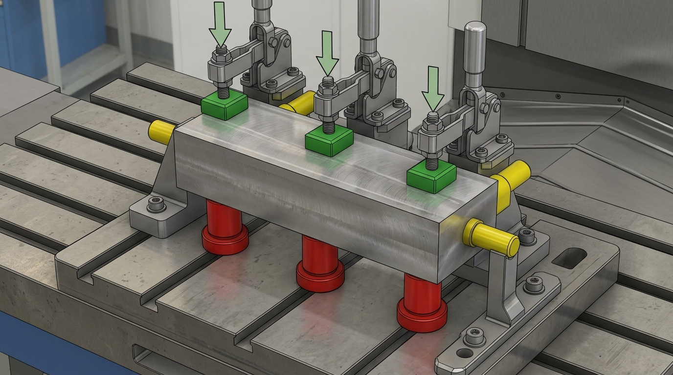
Locating, supporting, and clamping are different jobs:
| Function | Purpose | Common failure |
|---|---|---|
| Locating | Define the part's position and orientation | Redundant locators fighting each other |
| Supporting | Resist cutting forces and prevent deflection | Missing support under thin sections |
| Clamping | Hold the part against locators and supports | Clamp force distorting the part |
Carr Lane's fixture design guidance describes the 3-2-1 principle (three locators on a primary surface, two on a secondary surface, and one on a tertiary surface) and states that locators should take the main cutting forces, that clamps should push the part toward its locators or supports, and that clamping should secure the part without changing its shape. It also warns that redundant locators controlling the same direction can shift the part and reduce accuracy.
Check for clamping distortion
Thin or flexible parts can be machined accurately while clamped and then spring into a different shape when released. A theoretical model of a 3-2-1 fixture published in Acta Technica Napocensis shows how elastic and contact deformations of the locators under clamping and cutting forces can produce workpiece displacement and rotation, and therefore location and machining errors. A practical check is to measure critical features both clamped and unclamped during process development.
Choose stable reference features
Reference surfaces, holes, or features used in the next operation should be stable enough to locate reliably. A rough or distorted surface makes a poor secondary datum.
Know what a zero-point system can and cannot do
Zero-point clamping systems can make loading faster and more repeatable between machines or setups. They locate the pallet or fixture repeatably; they do not correct a poor datum choice, clamping distortion, or a mismatch between the fixture's locating features and the part's functional datums.
Transfer Datums with Reference Features and Controlled Offsets
When a critical relationship cannot be completed in one setup, the datum has to be carried from one operation to the next with as little added uncertainty as possible.
Use probing with known uncertainty
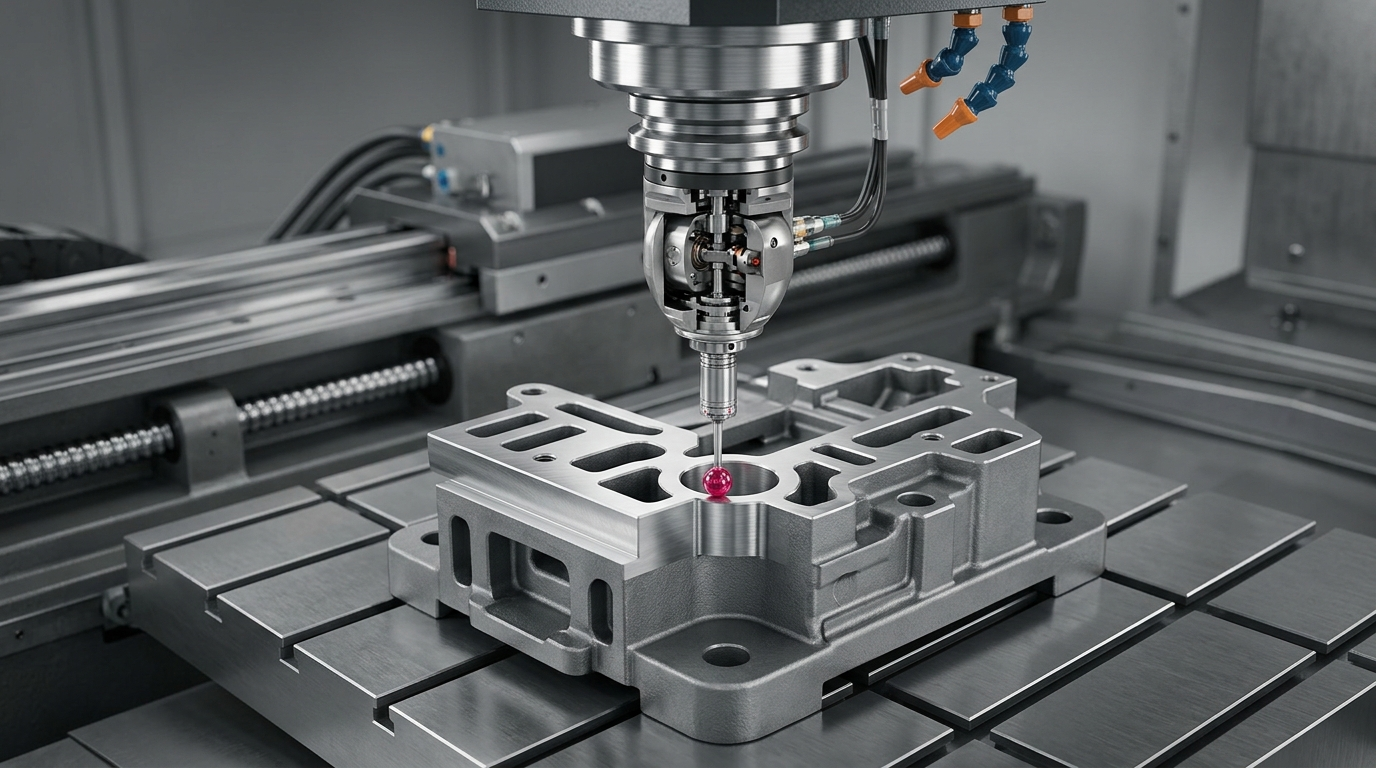
On-machine probing can re-establish a datum after relocation, but the probe measurement has its own uncertainty. ISO 230-10:2022 provides test procedures for evaluating the measuring performance of probing systems on numerically controlled machine tools; it does not assess the machine tool's own performance as a coordinate measuring machine. Before using probing to transfer a datum on a tight relationship, understand the probing system's measured performance on that machine. Where the relationship is critical, the transferred result can be confirmed off-machine by CMM inspection during process development.
Preserve process datums where the design allows
Dedicated tooling holes, reference pads, or machined reference faces can be added and maintained through the process specifically to carry the coordinate system from one operation to the next. Where the design permits, keeping them until the final operation, or removing them only in the last setup, preserves a consistent reference.
Record offsets instead of relying on memory
Record work offsets, probe results, the fixture identification, and the program revision for each setup. When a problem appears later, these records show whether the transfer or the cut caused it.
Align machining and inspection coordinate systems
The datum used to set up machining and the datum used by inspection should be the same, or their relationship should be known. If production machines from one reference and inspection aligns to another, both can report "in tolerance" while the part fails at assembly. Our quality assurance process selects the inspection method, including CMM inspection, according to the part and its requirements, so the inspection datum can be agreed together with the machining plan.
Estimate and Reduce Stack-Up Across Operations
Before deciding how to reduce stack-up, estimate how large it is and which contributor dominates.
Treat each step as a contributor
List each setup, locating feature, and measurement step that contributes to a critical relationship, with its estimated variation. This simple list often reveals that one transfer dominates the stack.
Know what worst-case and RSS calculations assume
Worst-case (arithmetic) stacking adds the tolerances of all contributors. In a review of tolerance stack methods, Fritz Scholz of Boeing describes it as the conservative benchmark: it relies on very minimal assumptions but assumes all parts meet their individual tolerances. Statistical (root sum square, RSS) stacking assumes, in its basic form, that contributors vary randomly and independently according to a normal distribution centered at the tolerance midpoint with ±3σ covering the tolerance; Scholz notes that practice has shown results are usually not quite as good as advertised, which led to models that allow wider distributions and mean shifts.
In multi-setup machining, those assumptions deserve scrutiny. A fixture offset or a locator error can be systematic, repeating on every part in the same direction, rather than random. Systematic contributors behave more like mean shifts and should not be combined as if they were independent random variation.
Choose the right intervention
Once the dominant contributor is known, compare the options:
• reduce the number of setups so that the critical relationship is machined in one clamping; • choose a better datum that matches function and inspection; • improve support or reduce clamping distortion; • improve single-operation capability where the operation itself is the limit.
Do not use a fixture supplier's repeatability claim as a substitute for part-level evidence. A catalog value describes the fixture under the supplier's test conditions, not your part, your clamping, and your probing method.
Measure Setup-to-Setup Variation Instead of Assuming It
Two comparisons reveal what the process is actually doing:
1. Within-setup variation. Measure the same features on several parts from one setup. 2. Between-setup variation. Measure the relationship between features cut in different setups across the same parts.
If between-setup variation is much larger than within-setup variation, the transfer is the problem. Record the sampling plan and the coordinate system used for each measurement, so that measurements are comparable. Feed the observed variation back into the datum scheme and workholding design, then document the reproducible loading, probing, offset, and inspection conditions in the process plan.
Where the part allows it, the most direct way to reduce stack-up is to remove setups altogether. Our multiaxis machining service uses 4-axis and 5-axis strategies to machine several sides without repeatedly repositioning the part, which helps maintain positional relationships between critical features.
Frequently Asked Questions
The following questions summarize the points that most often cause confusion when multi-setup parts are planned or audited.
What causes tolerance stack-up between CNC setups?
Relocating the part introduces variation from locating surfaces, fixture condition, clamping distortion, offset or probing uncertainty, and differences between machining and inspection references. Each relocation adds contributors that did not exist in the first operation.
Should I use worst-case or RSS for multi-setup stack-up?
Worst-case is conservative and needs minimal assumptions. RSS assumes independent, random, centered variation. Setup errors are often systematic, so RSS can be optimistic unless those contributors are treated as mean shifts or measured directly.
Does a zero-point clamping system eliminate setup error?
No. It improves repeatable location of the fixture or pallet but does not correct datum choice, clamping distortion, or offset errors at the part.
Can I mix ASME and ISO datum terminology?
It is better not to. ASME Y14.5 and ISO 5459 each define their own rules and terms. State which system the drawing uses and apply it consistently in machining and inspection.
How do I prove setup-to-setup repeatability?
Compare within-setup variation of features on several parts with between-setup variation of relationships across those parts, using a documented coordinate system and sampling plan.
Conclusion
Controlling CNC tolerance stack-up across multiple setups starts with datums chosen from function and inspection, not from loading convenience. Treat locating, supporting, and clamping as separate sources of variation, transfer datums with features and probing whose uncertainty is understood, and align machining and inspection references. Question the assumptions behind stack-up calculations, and measure setup-to-setup variation rather than assuming a fixture removes it. A useful process plan makes the datum scheme, offsets, and inspection reference reproducible.