Due to the variations in the manufacturing process, the size and dimension of the manufactured project are different from the original CAD model. In order to better control and communicate these variations, engineers and manufacturers use a symbolic language called GD&T(Geometric Dimensioning and Tolerancing).
GD&T is used to define the nominal (theoretically perfect) geometry of parts and assemblies, to define the allowable variation in form and possible size of individual features, and to define the allowable variation between features.
Dimensioning specifications define the nominal, as-modeled or as-intended geometry. One example is a basic dimension.
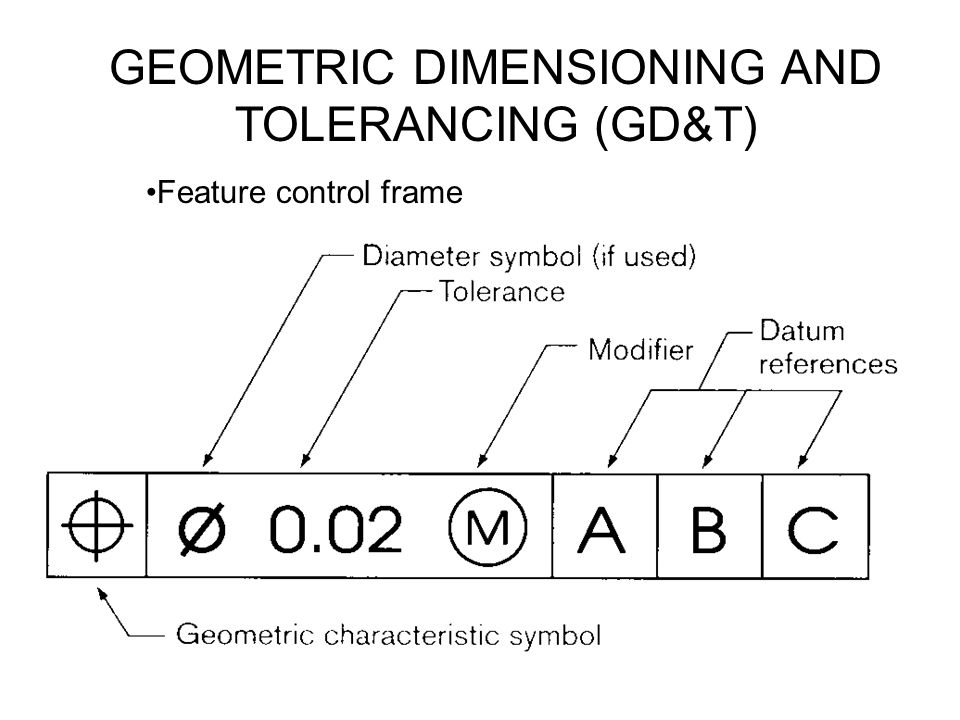
Tolerancing specifications define the allowable variation for the form and possibly the size of individual features, and the allowable variation in orientation and location between features. Two examples are linear dimensionsand feature control frames using a datum reference.
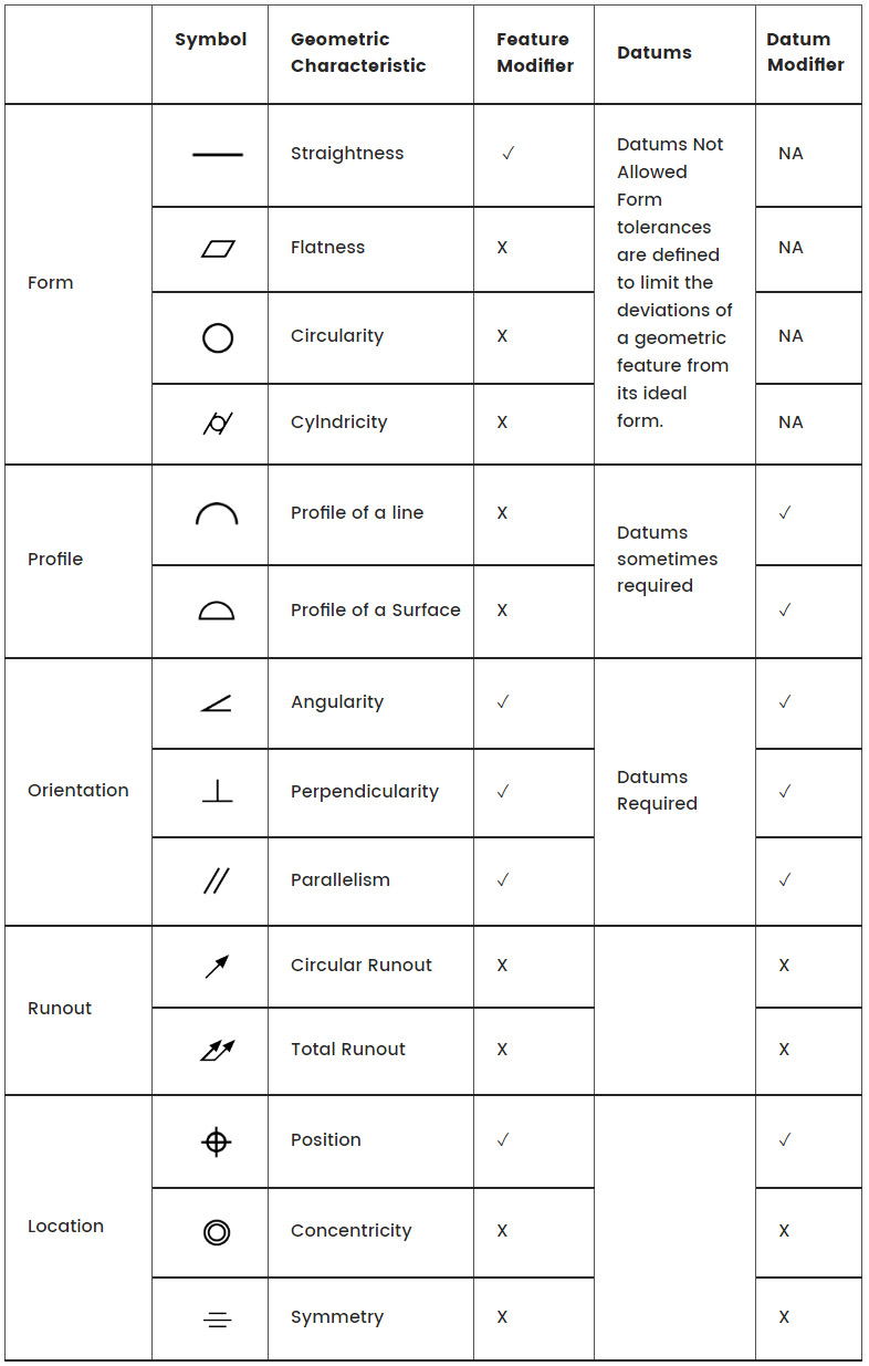
Common GD&T Symbols
Symbol
Geometric Characteristic
Feature Modifier
Datums
Datum Modifier
Form
Straightness
✓
Datums Not AllowedForm tolerances are defined to limit the deviations of a geometric feature from its ideal form.
NA
Flatness
X
NA
Circularity
X
NA
Cylndricity
X
NA
Profile
Profile of a line
X
Datums sometimes required
✓
Profile of a Surface
X
✓
Orientation
Angularity
✓
Datums Required
✓
Perpendicularity
✓
✓
Parallelism
✓
✓
Runout
Circular Runout
X
X
Total Runout
X
X
Location
Position
✓
✓
Concentricity
X
X
Symmetry
X
X
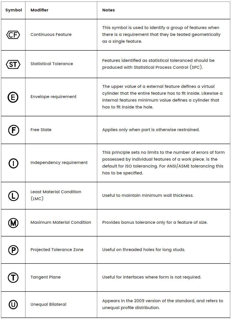
Modifiers
If no modifier follows a datum feature size, the datum feature applies regardless of material boundary.
Symbol
Modifier
Notes
Continuous Feature
This symbol is used to identify a group of features when there is a requirement that they be teated geometrically as a single feature.
Statistical Tolerance
Features identified as statistical toleranced should be produced with Statistical Process Control (SPC).
Envelope requirement
The upper value of a external feature defines a virtual cylinder that the entire feature has to fit inside. Likewise a internal features minimum value defines a cylinder that has to fit inside the hole.
Free State
Applies only when part is otherwise restrained.
Independency requirement
This principle sets no limits to the number of errors of form possessed by individual features of a work piece. is the default for ISO tolerancing.
For ANSI/ASME tolerancing this has to be specified.
Least Material Condition (LMC)
Useful to maintain minimum wall thickness.
Maximum Material Condition
Provides bonus tolerance only for a feature of size.
Projected Tolerance Zone
Useful on threaded holes for long studs.
Tangent Plane
Useful for interfaces where form is not required.
Unequal Bilateral
Appears in the 2009 version of the standard, and refers to unequal profile distribution.
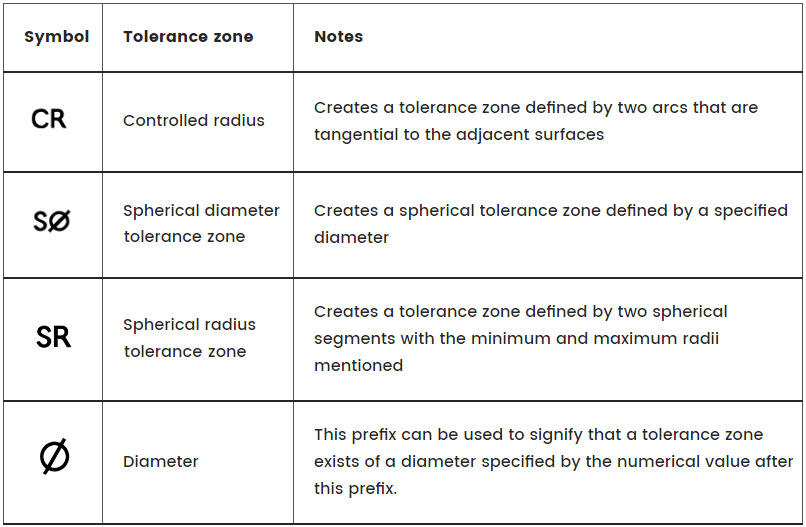
Tolerance Zones
Specifies the type of zone applied to the tolerance.
Symbol
Tolerance zone
Notes
Controlled radius
Creates a tolerance zone defined by two arcs that are tangential to the adjacent surfaces
Spherical diameter tolerance zone
Creates a spherical tolerance zone defined by a specified diameter
Spherical radius tolerance zone
Creates a tolerance zone defined by two spherical segments with the minimum and maximum radii mentioned
Diameter
This prefix can be used to signify that a tolerance zone exists of a diameter specified by the numerical value after this prefix.
Ready to Work On your Next Project?
Let us help you provide high quality parts in short time. Get your project started now!