Skip to content

ENGINEERING RESOURCES

Design Tips for Better
Manufactured Parts

Explore practical design guidance for injection molding, CNC machining, die casting and sheet metal fabrication—from early concepts to production-ready parts.

  • Design for Manufacturability
  • Material & Process Selection
  • Cost & Lead-Time Optimization

DESIGN WITH PRODUCTION IN MIND

Practical Design Guidance for Every Manufacturing Process

Explore process-specific recommendations that help improve manufacturability, control costs and prepare your parts for production.

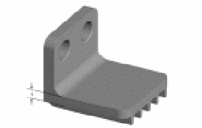
Injection molded plastic housing showing wall thickness ribs and bosses
01

DESIGN TIPS FOR

Injection Molding

Design details influence filling, cooling, ejection and final part stability.

PLASTIC PART DESIGN

Design Plastic Parts for Consistent Molding

Well-designed molded parts fill more consistently, cool more evenly and release from the tool with less risk of distortion or visible defects.

Maintain Uniform Wall Thickness

Use balanced sections and gradual transitions to reduce sink, warpage and uneven cooling.

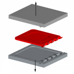
Add Appropriate Draft Angles

Provide sufficient draft based on feature depth, material and surface texture.

Design Ribs and Bosses Correctly

Size reinforcing features carefully to improve strength without creating thick sections.

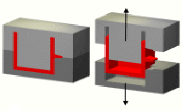
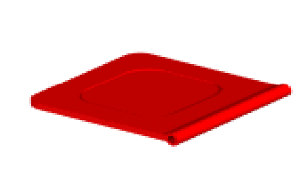
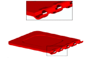
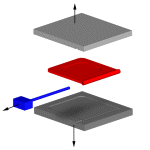
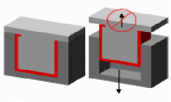
Minimize Unnecessary Undercuts

Simplify side features where possible to reduce sliders, lifters and tooling complexity.

Consider Gates and Parting Lines

Review gate position and mold separation early to protect appearance and filling performance.

View All Injection Molding Design Tips

MACHINED PART DESIGN

Design CNC Parts for Efficient Machining

Practical CNC design decisions can improve tool access, reduce machining setups and help maintain consistent dimensional accuracy.

01

Add Practical Internal Corner Radii

Match internal radii to standard cutting tools instead of specifying sharp internal corners.

02

Provide Clear Tool Access

Keep critical surfaces and features accessible from practical machining directions.

03

Avoid Unnecessarily Deep Cavities

Reduce excessive depth-to-width ratios to limit tool deflection and extended machining time.

04

Use Tight Tolerances Selectively

Apply close tolerances only to dimensions that directly affect fit, function or assembly.

05

Standardize Holes and Threads

Use common drill sizes, thread standards and sufficient depth clearance whenever possible.

View All CNC Machining Design Tips
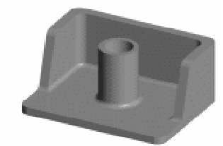
CNC machined aluminum housing showing internal internal corner radii and tool access
02

DESIGN TIPS FOR

CNC Machining

Tool access and feature geometry directly influence machining time and cost.

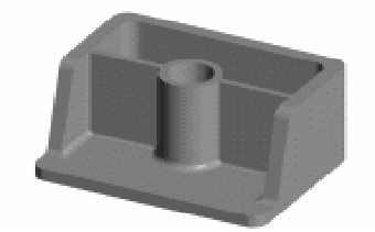
Die-cast aluminum housing showing wall transitions draft fillets and ribs
03

DESIGN TIPS FOR

Die Casting
KEY DESIGN FOCUS Stable Metal Flow
Balanced Walls
Proper Draft
Smooth Transitions

CAST PART DESIGN

Design Die-Cast Parts for Reliable Production

Effective die-cast part design supports stable metal flow, consistent cooling, reliable ejection and better dimensional control.

Keep Walls Consistent

Avoid abrupt thickness changes that can create porosity, shrinkage and uneven cooling.

Include Adequate Draft

Apply draft to walls, ribs and bosses to support reliable release from the die.

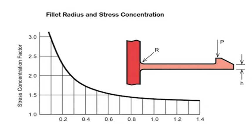
Use Fillets and Radii

Replace sharp transitions with suitable radii to improve flow and reduce local stress.

Optimize Ribs and Bosses

Support functional features without creating isolated heavy sections or hot spots.

Plan Parting, Ejection and Metal Flow

Consider parting lines, ejector locations, gates and overflow areas early to protect appearance and performance.

COMMON DIE-CAST MATERIALS

Aluminum Alloys Zinc Alloys
View All Die Casting Design Tips

FABRICATED PART DESIGN

Design Sheet Metal Parts for Accurate Forming

Good sheet metal design considers material thickness, bend behavior, feature spacing and assembly requirements before fabrication begins.

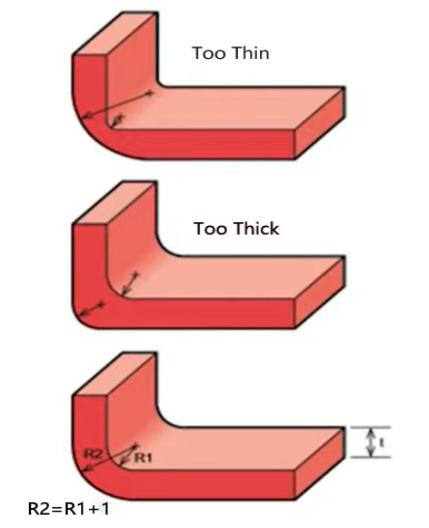
Use an Appropriate Bend Radius

Match the inside bend radius to material type, thickness and forming method.

Keep Holes Clear of Bend Lines

Maintain sufficient distance between holes, slots and bends to reduce distortion.

Add Bend Relief Where Needed

Use relief cuts near corners and flange intersections to prevent tearing or material buildup.

Design Practical Flanges

Provide enough flange length for accurate forming, fastening and final assembly.

Plan Joining and Assembly Early

Consider weld access, fasteners, hardware and alignment features during part design.

View All Sheet Metal Design Tips
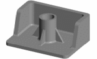
Sheet metal enclosure showing bend radius reliefs hole spacing and flanges
04

DESIGN TIPS FOR

Sheet Metal Fabrication

DESIGN CHECK

Forming-Ready Features
R

Bend Radius

D

Hole Distance

F

Flange Length

CORE DFM PRINCIPLES

Five Design Decisions That Shape Production

Before process-specific details are considered, these five decisions often have the greatest influence on manufacturability, part quality and overall production cost.

GEOMETRY

Simplify Where Possible

Remove unnecessary features and avoid geometry that creates difficult tooling, machining or assembly conditions.

WALL DESIGN

Keep Sections Consistent

Balanced wall sections support stable material flow, predictable cooling and more consistent part quality.

TOLERANCES

Specify What Matters

Apply tight tolerances only to functional features where they are genuinely required.

MATERIAL & PROCESS

Choose Them Together

Material properties, geometry, volume and performance requirements should guide process selection.

ASSEMBLY & FINISH

Plan Beyond the Part

Consider joining, secondary operations and surface finishing early in the design process.

The best time to resolve manufacturing risks is before tooling or production begins.

Request a Design Review

ENGINEERING DESIGN REVIEW

Is Your Design Ready for Production?

Send us your CAD files and project requirements. Our engineering team can review the design, material, tolerances and manufacturing process before production begins.

Manufacturability review

Material and process recommendations

Cost and lead-time evaluation

01 What is design for manufacturability?

Design for manufacturability, or DFM, is the process of reviewing a product design to ensure it can be manufactured reliably, efficiently and at an appropriate cost. It considers geometry, materials, tolerances, tooling, assembly and the selected manufacturing process.

02 When should a DFM review be completed?

A DFM review should ideally be completed before tooling, programming or production begins. Reviewing the design early makes it easier to correct potential issues without causing unnecessary delays or modification costs.

03 Which CAD file formats can I submit?

STEP, STP, IGES, X_T and SLDPRT files are commonly used for three-dimensional design review. Please also provide a PDF drawing when critical dimensions, tolerances, threads, finishes or inspection requirements need to be specified.

04 Can HordRT recommend the right manufacturing process?

Yes. Our engineering team can evaluate the geometry, material, production quantity, tolerances, surface finish and application before recommending a suitable manufacturing process.

05 How do tight tolerances affect manufacturing cost?

Tight tolerances may require additional machining operations, specialized equipment, slower production and more frequent inspection. They should mainly be applied to dimensions that directly affect function, fit or assembly.

06 Can a DFM review help reduce tooling costs?

Yes. Simplifying undercuts, improving draft, adjusting wall thickness and reviewing parting-line or ejection requirements can reduce tooling complexity and lower the risk of later modifications.

07 What information should I provide for a design review?

Please provide the 3D CAD file, technical drawing, preferred material, estimated production quantity, surface finish, application and any critical dimensional or functional requirements.

Get Quote
Get instant pricing, project lead times, and DFM feedback.
doc|docx|ppt|pptx|pdf|jpg|png|STEP|STP|STL|ZIP|RAR
IGES|IGS|SLDPRT|3DM|SAT or X_T files