-1.png)

Acceptable-looking parts after a first mold trial do not prove that the mold, process, and production system are acceptable. Without cavity identity, measurement conditions, process data, and an issue list, the next team cannot reliably explain or reproduce the result.
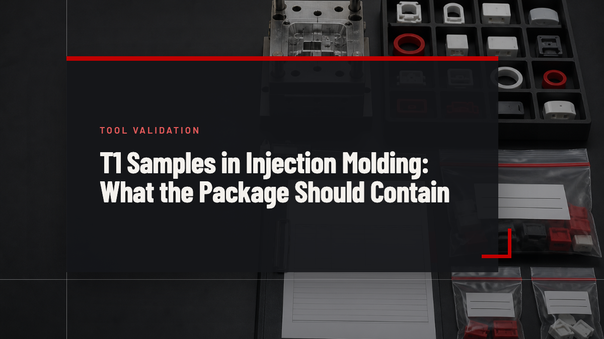
For T1 samples in injection molding projects, the package should answer three separate questions:
-
What do the sampled parts show under the agreed inspection conditions?
-
What machine, material, mold, and process state produced those parts?
-
What is the current condition of the tool, and what action is authorized next?
The exact deliverables must be defined by the drawing, purchase order, quality plan, and customer-specific requirements. There is no universal file count or sample quantity that turns a T1 trial into formal production approval.
Do Not Treat T1, FAI, and PPAP as Synonyms
A T1 trial is normally a development event: an early opportunity to run a new or substantially changed mold and assess filling, release, dimensions, cosmetics, cooling, or automation.
A formal first article inspection (FAI) is different. SAE AS9102C establishes requirements for performing and documenting FAI and states that it is complementary to customer, statutory, and regulatory requirements. [1] Production Part Approval Process (PPAP) is different again: AIAG describes PPAP as evidence from an actual production run at production rates that the process can consistently meet design and specification requirements. [2]
| Event | Primary question | Why the label matters |
|---|---|---|
| T1 mold trial | Can the current tool and provisional process produce informative samples? | Development conditions may not represent a stable production process |
| Contractual FAI | Does documented first-production evidence satisfy the applicable FAI requirements? | Scope and forms come from the governing customer or industry requirement |
| PPAP or equivalent production approval | Can the production-intent process repeatedly meet all requirements at the intended rate? | A successful development trial does not replace production approval |
Call a T1 package an FAI or PPAP submission only when the contract requires that route and every applicable requirement has been met. Otherwise, describe it accurately as a tool-trial evidence package.
Freeze the Acceptance Basis Before the Trial
Before molding begins, record:
-
part, drawing, CAD, mold, cavity, and insert revisions or identifiers;
-
exact resin grade, color/additive package, supplier, and substitution rules;
-
trial objective, intended machine requirements, and known non-production conditions;
-
sample quantity, cavity coverage, selection method, labeling, and retention needs;
-
dimensional, visual, functional, material, and internal-defect requirements;
-
conditioning, measurement methods, fixtures, decision rules, and acceptance authority.
ISO 20457:2026 provides plastics-molding guidance for geometry, dimensional tolerances, and acceptance conditions, but it does not cover surface imperfections such as sink marks, flow structures, roughness, or joint lines. [3] Consequently, “to ISO 20457” does not replace an agreed cosmetic standard, viewing conditions, limit samples, or functional test criteria.
Layer 1: Make Each Submitted Part Traceable
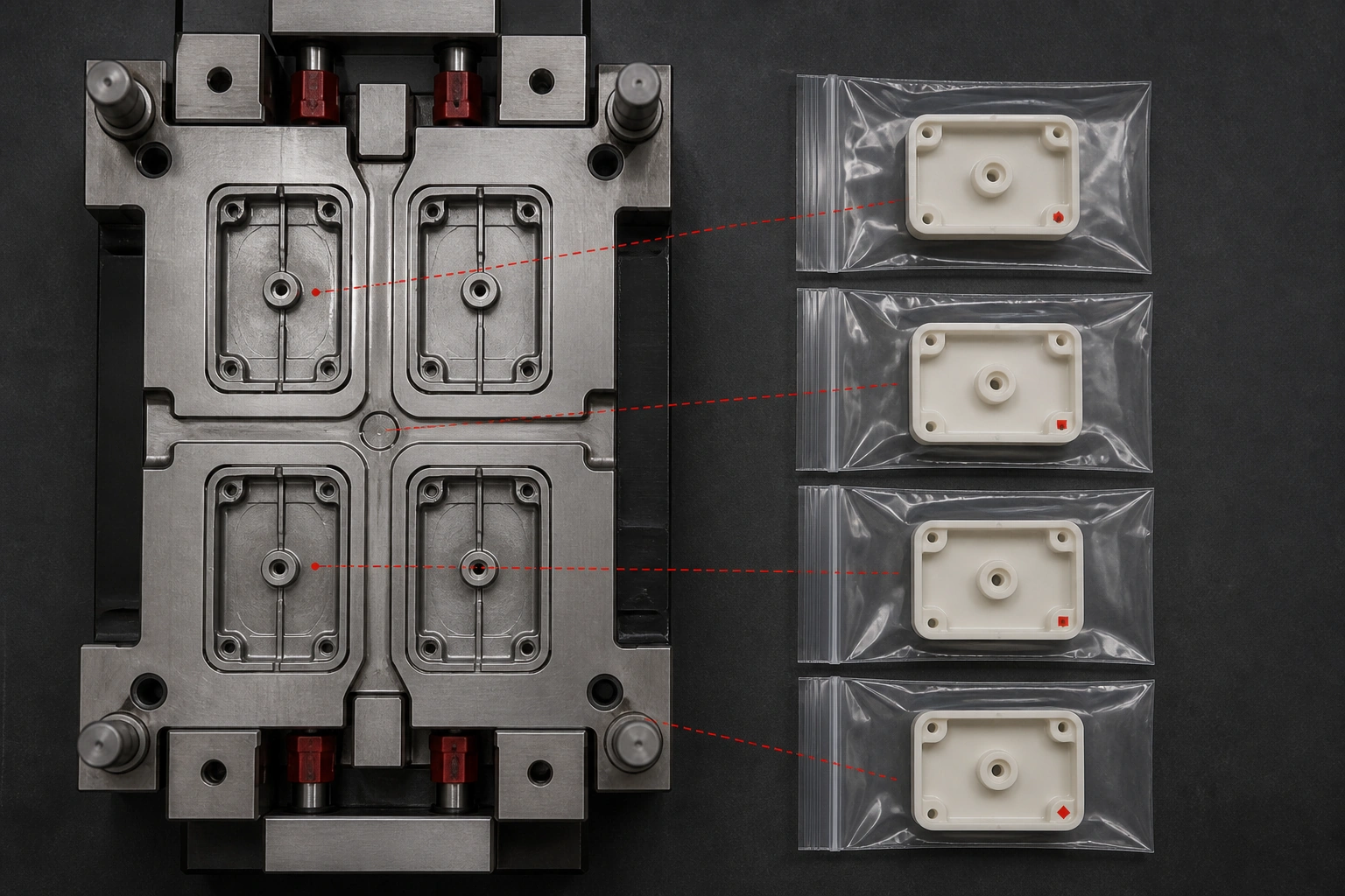
The sample itself should connect to the report. Identify the part revision, cavity, trial, resin lot, and sample sequence or molding-time band. If individual shot numbering is impractical, document the selection method. Keep setup and purge parts separate from measured samples.
The part-level report should include:
-
requirement ID, nominal, tolerance, result, units, method, and status;
-
cavity and sample identity for every value;
-
deviations, omissions, conditional results, and their reasons;
-
controlled cosmetic photographs where appearance matters;
-
weight trends when used as a diagnostic; and
-
functional results under specified mating-part and fixture conditions.
ISO 10012:2026 addresses measurement management systems intended to provide confidence that results are valid, reliable, and fit for purpose. [4] ISO 14253-1:2017 establishes decision rules that consider measurement uncertainty when proving conformance or nonconformance. [5] A rounded value and green “pass” cell can hide decision risk near a tolerance limit.
State when and how parts were conditioned. ISO 291 defines standard atmospheres for conditioning and testing plastics; ASTM D955 measures molding shrinkage on specified specimens at stated intervals, including 24 and 48 hours. [6][7] Neither makes one waiting period universally correct for production parts. Material, geometry, storage, and customer requirements can change the relevant state. Do not mix warm, as-molded, and conditioned results.
A 30-Shot T1 Run Does Not Automatically Support Cpk
Thirty consecutive shots can reveal useful short-term patterns. They may show warm-up drift, cavity-to-cavity offsets, intermittent sticking, weight changes, or an unstable transfer. They do not, by themselves, establish process capability.
NIST defines capability in the context of a stable, in-control process and notes that estimates require substantial independent data and distribution assumptions. [8] Its sample-size guidance also shows that no single number is correct without defined error rates, detectable change, and variation assumptions. [9]
At T1, report individual values, mean, range, cavity differences, time order, and observed special causes. Calculate Cp or Cpk only under a defined method with a stable, production-intent process, adequate measurement system, and representative sampling. Preserve cavity identity because a pooled index can conceal different cavity centers or spreads.
For identical cavities, name the cavity-weight comparison instead of reporting an undefined "balance percentage." One transparent option is the cavity-to-cavity mean-weight spread:
(maximum cavity mean - minimum cavity mean) / grand mean × 100%
Report that value with each cavity mean, the within-cavity variation, shot order, and the handling of runner or sprue weight. The equation defines the metric; it does not define a universal acceptance limit. Family molds or intentionally different cavities require normalized, feature-specific measures rather than this identical-cavity comparison.
Layer 2: Preserve the Process That Produced the Samples
A setpoint shows what was requested; a machine trace or actual value shows what occurred. Capture, as applicable:
-
machine, injection-unit, screw, clamp, mold orientation, and auxiliaries;
-
resin grade and lot, regrind, drying, and moisture result when required;
-
barrel, nozzle, hot-runner, and mold temperatures;
-
injection stages, transfer, pressure limit and peak, pack, position, cushion, recovery, and back pressure;
-
fill, cooling, total cycle, actual ejector stroke and timing, evidence of sticking or part deformation, and automation timing;
-
coolant connections and thermal data when relevant; and
-
each authorized change and the samples produced after it.
Separate a nominal T1 condition from a process-window study. If robustness is in scope, plan controlled conditions, define outputs, and keep their samples distinct. Staged short shots can help evaluate fill sequence, air traps, weld lines, or balance; they are not mandatory for every mold.
Weight and cycle time are useful trends, not stand-alone acceptance results. Stable weight can coexist with dimensional failure, and a target cycle can hide inadequate cooling. Connect each measure to the characteristic it is meant to explain.
Internal Inspection Must Have a Defined Method and Limit
Sectioning every thick feature is unnecessary when no internal requirement or credible defect risk exists. Conversely, a thick boss, optical feature, pressure boundary, bonded interface, or highly loaded area may justify destructive sectioning, microscopy, or industrial computed tomography (CT).
ISO 15708-3:2025 covers operation and interpretation of industrial CT and the relationship between CT performance parameters and system specifications. [10] It does not supply a universal void limit for molded plastic parts. A CT requirement should therefore name the region of interest, detectable defect type and size, scanning or reconstruction constraints, interpretation method, and acceptance criterion. A destructive section should likewise define sample location, cut plane, preparation, magnification, and limit. “CT passed” or an unlabeled cross-section photograph is not reproducible evidence.
Layer 3: Document the Tool State and Correction Boundary
The tool record should show what was tested: the current layout or as-built drawing, cavity and insert IDs, component list, gate and runner status, tool revision, open deviations, relevant photographs, and correction history linked to part results.
Additional mold acceptance documentation should be risk- and contract-based:
| Conditional record | Include it when | What it helps control |
|---|---|---|
| Steel, heat-treatment, or hardness record | Material, life, wear, or repairability is specified | Tool-material traceability |
| Insert dimensional report | Interchangeability or a critical feature depends on it | Insert conformity |
| Roughness or texture record | Release, sealing, optics, friction, or appearance depends on it | Functional surface condition |
| Vent baseline | Vent geometry is controlled or diagnostic | Reference for gas-related changes |
| Cooling layout, pressure test, flow, or balance | Cycle, warpage, or thermal consistency is specified | Circuit integrity and heat removal |
| Coating record | Treatment affects wear, release, corrosion, or dimensions | Coating and dimensional consequence |
| Ejection and manual fitting or spotting record | Release depends on a controlled ejector stroke, or slides, shutoffs, inserts, and contact faces were hand-fitted or corrected | Actual ejection travel, contact condition, material removed, responsible revision, and repeatability of the as-tested tool |
| Spares and maintenance list | Production support is in the agreement | Replacement and maintenance scope |
Do not demand every item merely to make the package look complete. Do not omit one when the drawing, tool specification, validation plan, or observed failure makes it necessary.
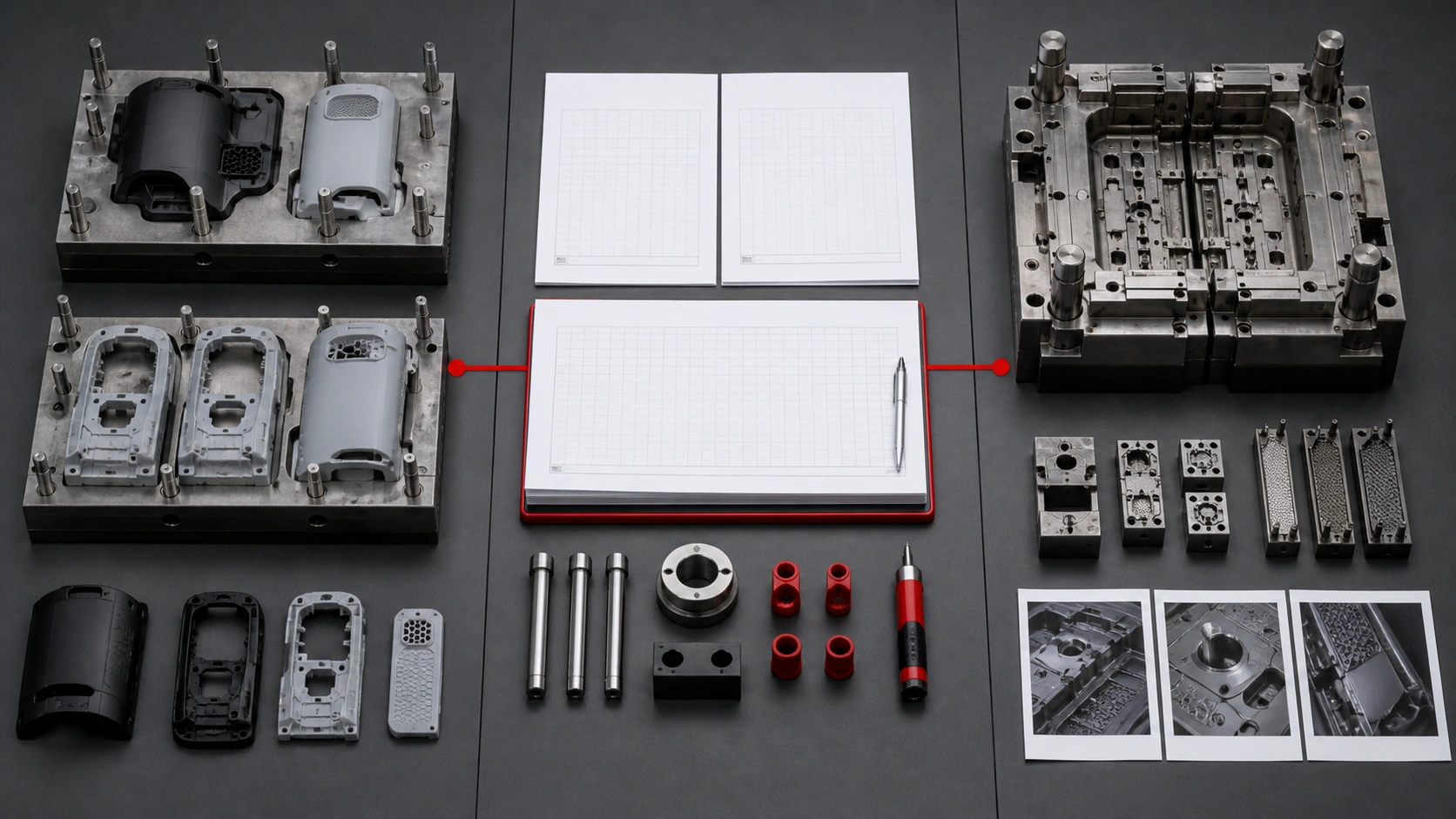
A One-Page T1 Package Gate
| Evidence group | Core or conditional? | Release question |
|---|---|---|
| Scope, revisions, material, mold, machine, objective | Core | Is the tested state identifiable? |
| Labeled samples and selection record | Core | Is each result traceable to cavity and condition? |
| Dimensional, visual, and required functional results | Scope-defined core | Are requirements passed or dispositioned? |
| Method, conditioning, and decision rule | Core for acceptance | Is each decision defensible? |
| Settings, actuals, changes, and cycle | Core | Can the condition be understood and repeated? |
| Capability indices | Conditional | Was a stable, representative study performed? |
| CT, sectioning, moisture, material, or special tests | Conditional | Is the test tied to a risk and limit? |
| Tool revision, issue list, and correction history | Core | Does the record match the tested tool? |
| Steel, roughness, cooling, coating, and spares | Conditional | Does the tool plan require them? |
| Signed disposition and next-trial plan | Core | Is the next action authorized? |
Close T1 With a Controlled Correction Loop
Each failed or uncertain characteristic should become a traceable issue with its requirement, evidence, suspected mechanism, proposed action, owner, date, and verification method. Separate reversible process experiments from irreversible steel changes. Before cutting steel, confirm repeatability, measurement suitability, correction direction, and the remaining adjustment stock.
The next trial plan should specify which issues are expected to close, which evidence must be repeated, and what remains unchanged. This turns T2 into a verification event rather than another exploratory run.
Our rapid tooling service and first article inspection guide provide public scope and planning context. Our inspection workflow states that DFM review considers tolerances and potential quality issues, raw-material certificates of analysis are checked, and a full-dimensional inspection report follows T1 samples. A project using those checkpoints should still place its sample quantity, cavity coverage, special tests, capability expectations, tool records, and acceptance authority in the purchase and quality documents rather than assume they are included by the label “T1.”
Frequently Asked Questions
How many T1 samples should each cavity provide?
There is no universal number. Choose it from the trial objective, number of cavities, destructive and nondestructive tests, expected variation, customer retention needs, and any statistical study plan. More unlabeled parts do not improve the evidence package.
Should every cavity receive a full-dimensional inspection?
If cavity-specific geometry can affect acceptance, every cavity should at least be covered for the relevant characteristics. Whether every characteristic is measured on every cavity and sample is a contract and risk decision. State the matrix explicitly.
Can acceptable T1 dimensions release the mold for production?
Only if the agreed release plan says so and all other requirements are satisfied. T1 dimensions do not automatically prove process stability, rate capability, tool durability, cosmetics, material compliance, or production approval.
Conclusion
A defensible package for T1 samples injection molding connects the parts, process, and physical tool through a single traceable record. Define the acceptance basis before the run, identify samples by cavity and trial condition, report measurement state and uncertainty-aware decisions, preserve actual process data, and distinguish useful T1 trends from formal capability. Add CT, sectioning, steel, cooling, coating, or maintenance evidence only when the specification or risk requires it. Finally, close every open result through a controlled correction and verification plan. That is what turns a box of first-off parts into an engineering decision package.
Sources
[1] SAE International: AS9102C, Aerospace Series—First Article Inspection Requirements
[2] AIAG: Production Part Approval Process (PPAP), Fourth Edition
[8] NIST/SEMATECH: What Is Process Capability?