A molded housing passes color review at the molder, then fails at the customer's incoming inspection. Both sides are confident. Both may be right, because they looked at the part under different lights, compared it with different references, or measured it with different instrument settings. In injection molding color matching, many disputes are not caused by the pigment at all. They come from an approval method that was never fully defined.
Surface texture, gloss, wall thickness, the viewing face, the light source, the measurement geometry, and the color-difference equation all influence whether a part "matches." If any of these remain implicit, the first approved sample becomes difficult to reproduce, and later disagreements turn into arguments about numbers that were never comparable.
This article treats color approval as a controlled workflow: define the standard and conditions, measure with a stated method, separate first-part approval from production monitoring, and diagnose drift in an order that does not mistake a method change for a material change.
Why a Color Match Can Pass Under One Light and Fail Under Another
The most common reason for a "matching" part to fail elsewhere is metamerism. Two samples with different spectral reflectance curves can appear identical under one light source and different under another. A molded part colored with a different pigment combination from the master can therefore pass in a daylight booth and fail under store lighting or warm indoor lamps.
ASTM D1729, the practice for visual appraisal of opaque materials, notes that observers should have at least normal color vision and that simulated daylight is the usual primary reference. ASTM D4086 provides visual techniques for detecting illuminant and observer metamerism and estimating its magnitude; it does not cover gonioapparent (angle-dependent) samples such as metallic or pearlescent finishes. Where metamerism is suspected, ASTM D2244 directs users to verify instrumental color differences with D4086, because its color-difference equations were derived or optimized for daylight illumination.
Before any tolerance discussion, the parties should confirm three things:
1. Is the disagreement visual, instrumental, or both? A visual rejection with an acceptable instrument reading often points to a viewing-condition, gloss, or metamerism issue rather than a material shift. 2. Were both evaluations done under the same light sources and viewing conditions? If not, the results are not yet comparable. 3. Does the part match under a second, spectrally different light source? A match that holds under only one source suggests a formulation difference that process adjustment is unlikely to correct.
When the visual and instrumental results disagree, neither should automatically override the other. The disagreement itself is evidence that the method needs review.
Define the Master Standard, Surface Finish, and Viewing Conditions
A color decision is only as reproducible as the reference and conditions behind it, so the master, the surface it represents, and the way it is viewed need to be fixed before any part is judged.
Choose what the master actually is
A color standard can be a color chip or plaque, an approved molded part, or a production reference part retained after launch. Each has a different role:
| Master type | Typical use | Main limitation |
|---|---|---|
| Color chip or plaque | Early formulation and supplier matching | May not share the part's texture, gloss, or thickness |
| Approved molded part | First-part approval | Represents one tool state and one material lot |
| Production reference part | Ongoing production comparison | Ages and can be damaged; requires controlled replacement |
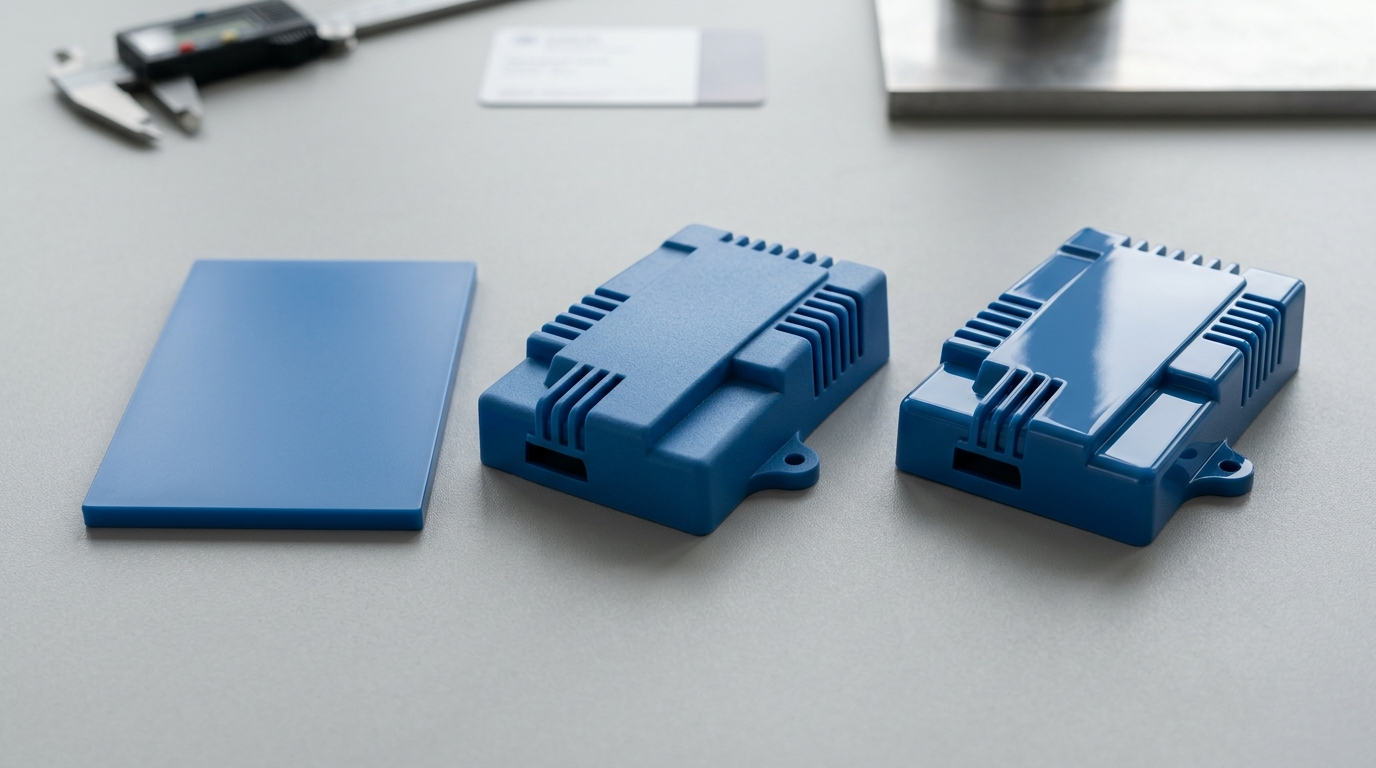
The master and the production part should share texture, gloss level, approximate wall thickness, and viewing face. A smooth plaque compared with a textured housing is not a like-for-like comparison, because surface structure changes how much light is reflected specularly versus diffusely. Konica Minolta's measurement guidance explains that a glossy and a matte surface of the same material can look different in color because observers mainly perceive the diffuse component and tend to ignore glare.
Specify the viewing conditions in writing
The approval document should state the primary light source (for example, a D65 daylight simulator), at least one secondary light source chosen to reveal metamerism, the background, the viewing angle and distance, and how the part is held. ASTM D1729 describes the equipment and procedures for diffusely illuminated opaque materials and excludes metallic and pearlescent materials, which require different viewing geometry. If the product has metallic effects, the approval method needs to address angle-dependent appearance separately. When parts are painted or printed after molding, the finished surface needs its own reference as well; our secondary processing workflow asks for the required color reference, gloss level, texture, and cosmetic criteria with the RFQ for this reason.
Control the master itself
Masters fade, scratch, and get handled. Record where each master is stored, who may issue it, how it is identified, when it expires or must be re-verified, and how a replacement is approved against the previous standard. An undocumented replacement master is a frequent cause of apparent drift that nobody can trace.
Use CIELAB and Delta E as Measurement Tools, Not a Standalone Pass/Fail Rule
Instruments make color comparison more objective, but only when everyone agrees on what the number represents and how it was obtained.
Know which Delta E you are using
CIELAB expresses color as lightness (L*), red-green (a*), and yellow-blue (b*) coordinates. Delta E summarizes the distance between two colors, but several equations exist. ASTM D2244-25 covers CIELAB (ΔE*ab), CMC, CIE94, DIN99o, and CIEDE2000 (ΔE00). The current definition of CIEDE2000 is published as ISO/CIE 11664-6:2022.
Two rules follow from ASTM D2244:
• Do not compare values from different equations. Color differences calculated in different color-scale systems are not likely to be identical, so a "ΔE 1.0" in CIELAB is not equivalent to "ΔE 1.0" in CIEDE2000. • The tolerance is an agreement, not a universal constant. D2244 states that the purchaser and seller should agree on the permissible tolerance, and that individual materials and conditions of use may require specific tolerances. It also highly recommends CIEDE2000 for small differences in the 0.0–5.0 ΔE*ab range.
For this reason, a drawing note such as "ΔE ≤ 1.0" is incomplete unless it also names the equation, illuminant, observer, measurement geometry, and averaging rule.
Define the measurement geometry
Many sphere spectrophotometers can measure with the specular component included (SCI) or excluded (SCE). SCE removes the gloss reflection and correlates more closely with how an observer sees the part; SCI measures total reflectance largely independent of surface condition and is often used for formulation work. On textured or gloss-varying molded surfaces, SCI and SCE readings can differ noticeably. The approval document should state which mode is used and why, and the same mode should be used by the molder and the customer.
Set the measurement points before approval
Specify measurement locations on the part, the aperture size, the number of readings per location, whether the instrument is repositioned between readings, and how readings are averaged. Textured surfaces in particular need several readings because a single small aperture may sample an unrepresentative area.
When the instrument is not enough
An instrumental pass does not cancel a controlled visual rejection if metamerism, angle-dependent effects, or texture are involved. ASTM D2244 itself points to visual verification under D4086 when metamerism is suspected. The workflow should define who performs the visual review, under which conditions, and how the result is recorded.
Build a First-Part and In-Process Color Approval Workflow
First-part color approval and routine production inspection answer different questions. First-part approval asks whether the tool, material, and process can produce the agreed color. Production inspection asks whether that state is being maintained. Color is one part of a broader first-trial record; the guide to what a T1 sample package should contain shows how cavity identity, measurement conditions, and process data fit together.
For first-part approval, record:
• resin grade and lot; • colorant or masterbatch identification, lot, and let-down ratio; • drying conditions and any regrind percentage; • key process settings, including melt temperature and cycle time; • cavity number and sample identity; • the master used, viewing conditions, instrument settings, equation, and readings.
For in-process inspection, define sampling positions, cavity identification, inspection frequency, and the reaction plan. Set the approval, hold, recheck, and escalation steps before production starts, not during the first dispute. A practical structure is:
1. Accept when the part meets the agreed instrumental and visual criteria. 2. Hold when a reading approaches the limit or a visual concern arises; remeasure under the documented method. 3. Escalate when a confirmed shift persists, triggering material and process review. 4. Reapprove when an agreed change is made.
This reaction plan belongs in the inspection plan rather than in an operator's memory. Our quality assurance team defines inspection points and reporting scope with customers according to the part's requirements, which makes the plan part of the agreed record.
Trace Color Drift to Material, Process, Surface, and Lighting Variables
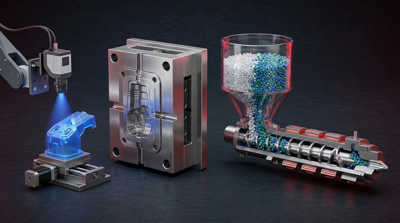
When a part drifts from the approved color, change the formulation last. Work through the variables in an order that rules out the cheapest explanations first.
Method first. Remeasure the master and the suspect part on the same instrument, in the same mode, at the same locations. If the master itself reads differently from its recorded values, the method or the master has drifted, not the production part.
Surface second. Check texture wear, gloss changes, mold release residue, and measurement position. A change in gloss can change perceived color and SCE readings without any change in the colorant.
Material third. Check resin lot, colorant lot, let-down ratio and dosing, regrind percentage, and drying. A new resin lot with a different base color, or inconsistent masterbatch dosing, can shift the part even with unchanged settings. Drying should be confirmed by evidence rather than assumed; see how to prove the resin is dry before attributing a shift to the colorant.
Process fourth. Colorant heat stability depends on temperature and exposure time. EN 12877-2 defines a method for determining the color stability of colorants to heat during processing by injection molding, and notes that the result is a relative value under defined conditions. This supports a practical inference: a change in melt temperature, residence time, or shear history may affect color for some colorant and resin combinations, so these settings belong in the approval record. The size of the effect is colorant- and resin-specific, which is why it should be checked rather than assumed.
A controlled remeasurement is the step that distinguishes color drift from method drift. Without it, a team can spend weeks adjusting a formulation to correct an instrument or master problem.
Control Color Across Cavities, Lots, and Production Changes
An approved color has to survive more than the first production run; cavities, material lots, and later changes each introduce their own risk of drift.
Compare cavities separately
In multi-cavity tools, cavities can differ in fill, cooling, and surface finish. Preserve cavity identification in samples and records, and evaluate each cavity against the master rather than averaging across cavities.
Define reapproval triggers
The approval document should list the changes that require color reapproval. Typical triggers include a new resin grade or supplier, a new colorant or masterbatch lot, a change of molding machine, a mold repair affecting texture or polish, a significant process change, and a change in a secondary process. If parts are painted, printed, or flocked after molding, color should be rechecked after that secondary process, because the final appearance is what the customer sees.
Keep everything in one controlled document
Put the light sources, instrument and mode, color-difference equation, illuminant and observer, measurement locations, number of readings, tolerance, master identity, and reapproval triggers into one controlled color approval document. When a dispute occurs, the first question should be "Did we follow the document?" rather than "Whose number is right?"
We treat color as part of documented sample approval: our tooling validation process includes review of color, texture, gloss, and visible molding defects against agreed criteria before the approved samples and process baseline are released for production.
Frequently Asked Questions
The questions below come up most often when buyers and molders set up or dispute a color approval.
What is a good Delta E tolerance for injection molded parts?
There is no universal value. ASTM D2244 states that buyer and seller should agree on the tolerance for the specific material and use, and that values from different equations are not interchangeable. A tolerance is meaningful only when the equation, illuminant, observer, geometry, and averaging rule are also specified.
Should I use SCI or SCE for molded parts?
SCE correlates more closely with visual appearance, while SCI measures total color largely independent of surface condition. Many appearance-driven approvals use SCE; formulation work often uses SCI. The key is that both parties use the same mode.
Why does a part match in the booth but not at the customer?
Likely causes include metamerism, a different light source, a different master, or different viewing geometry. Check the part under a second light source and confirm both sites use the same documented conditions.
Can process settings change the color of a molded part?
They can for some colorant and resin combinations. Colorant heat stability is evaluated under defined injection-molding temperatures and dwell times, so melt temperature and residence time should be recorded during approval and checked during drift investigations.
When does color need to be reapproved?
When the resin, colorant, machine, mold surface, process, or secondary process changes in a way that can affect appearance. List these triggers in the approval document before production.
Conclusion
Reliable injection molding color matching depends less on a single Delta E number than on a defined method. Approve the master, surface, and viewing conditions before debating the value. Use Delta E as a controlled measurement with a named equation, geometry, and averaging rule, not as a universal pass/fail rule. Separate first-part approval from production monitoring, and diagnose drift by checking method, surface, material, and process in that order. When the approval method is documented, the approved color can be reproduced after material lots, machines, and processes change.