

An eight-cavity mold can produce eight complete-looking parts while still experiencing eight different fill-and-pack histories. The first cavities to fill may already be packing while the last cavities are still filling. By the time the mold opens, hold pressure can make every part look complete and can partly conceal the original imbalance.

That is why “all cavities filled” is not a runner-balance acceptance criterion. For a multi-cavity feed system, the practical target is balanced and synchronized filling under defined material and process conditions. Autodesk describes its runner-balance objective in the same terms: equal pressure drop along the flow paths so that the cavities fill at the same time.[1]
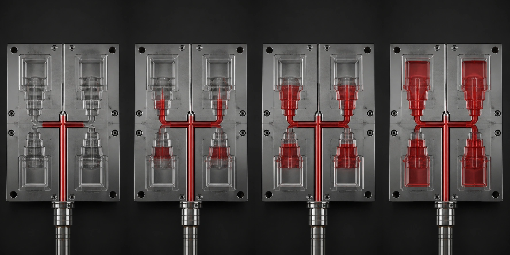
The most direct physical check is a staged short-shot study. It freezes the fill pattern before packing can overwrite the evidence. A second, full-part study then determines whether the cavities also produce comparable mass and stability under the approved process. The two tests answer different questions, and neither should be replaced by a photograph of one good production shot.
A Geometrically Balanced Runner Can Still Fill Unevenly
A naturally balanced layout gives equal nominal flow-path lengths and is the preferred starting point for identical cavities. It does not guarantee equal melt conditions at every gate.
In an H-pattern runner, the polymer develops velocity and temperature gradients as it travels through the runner cross-section. Successive branches divide and rotate those layers. The result can be a hotter, lower-viscosity portion of the melt feeding some cavities and a cooler portion feeding others. Beaumont, Young, and Jaworski documented severe shear-induced imbalance in geometrically balanced multi-cavity runner systems.[2] Later eight-cavity experiments used short shots to observe the same type of inner-to-outer flow difference and showed that injection speed, melt temperature, and mold temperature changed its magnitude.[3]
Recent work reinforces the boundary: runner diameter, gate area, polymer viscosity, filler, and molding process all affected the short-shot pattern in one eight-cavity test mold.[4] Other simulation-and-experiment research concluded that there is no universal process setting that eliminates imbalance across every material and runner layout; the material, runner geometry, and operating window must be evaluated together.[5]
This distinction matters during correction. A steel change that balances one resin at one fill rate may not remain balanced after a grade change or a large process shift. “Artificially balanced” does not mean “wrong,” but it does mean the validated conditions belong in the process specification.
Build the Study Around a Locked Baseline
A short-shot study is useful only when shot volume is the intentional variable. If resin moisture, melt temperature, mold temperature, screw recovery, non-return-valve leakage, or fill velocity changes between samples, the study mixes runner evidence with process noise.
Before collecting parts:
- Identify every cavity. Use permanent cavity numbers and keep the same physical layout in every photograph and data table.
- Stabilize the mold and machine. Run the approved resin grade, colorant, drying condition, barrel profile, mold-temperature setpoints, screw speed, back pressure, and fill-velocity profile until the process is thermally stable.
- Remove packing from the diagnostic. Set hold pressure and hold time to zero, or use an equivalent validated setup that prevents the packing phase from adding material after initial filling.
- Keep the velocity profile fixed. Create the stages by reducing delivered volume or the transfer position, not by inventing a different speed profile at each stage.
- Record actual conditions. Save material lot, moisture result when relevant, machine, mold, date, shot size, cushion, peak pressure, fill time, melt and mold temperatures, and any cavity-pressure data available.
The study should cover several representative points from early cavity entry through near-complete fill. A sequence such as 60%, 75%, 85%, and 95% total fill may be a workable project plan, but those percentages are not an industry standard. Very unequal cavities may need earlier steps; a hot-runner tool may need additional samples around valve-opening events. Define the steps before the trial and repeat enough shots at each step to show that the rank is reproducible rather than a one-cycle anomaly.
Read the Short Shots as a Sequence, Not a Single Snapshot
Lay out every shot by cavity number, photograph it from a fixed position, and measure an agreed fill indicator. For identical parts, the indicator may be part mass, projected filled area, flow length, or cavity volume filled. Research studies have used both short-shot flow length and mass to quantify imbalance.[3][4]
The most important result is the fill rank: which cavity leads, which lags, and whether that order persists as total fill increases.
| Observed pattern | Most defensible interpretation | Next check |
|---|---|---|
| The same cavities lead at every stage | A repeatable feed-system or cavity-flow asymmetry is likely | Compare gates, runner branches, vents, cavity geometry, and local temperatures |
| The rank reverses when fill rate or melt temperature changes | Shear/thermal behavior is interacting with the runner geometry | Map the process window before cutting steel |
| Early filling is similar, but near-full parts diverge | The problem may begin at gate restriction, venting, transfer, or the start of packing | Compare gate dimensions, end-of-fill pressure, and air traps |
| Short shots match, but full-part mass or dimensions do not | Initial runner balance is not the primary issue | Investigate packing, gate seal, cooling, and shrinkage by cavity |
| All cavities move up and down together from shot to shot | A common machine, material, or process input is more likely than one runner branch | Check cushion, check-ring repeatability, recovery, material, and temperature stability |
A short-shot study proves the observed filling order under the documented setup. It does not prove long-term dimensional capability, equal cooling, equal packing, an adequate process window, or balance with another resin. Those claims require their own data.
Use Full-Part Weights to Separate Between-Cavity and Within-Cavity Variation
After the short-shot study, restore the approved fill-and-pack process and collect consecutive full shots without mixing cavities. Weigh each part individually and preserve both the shot number and cavity number.
Two calculations are useful:
Cavity balance spread (%) =
100 × (maximum cavity mean − minimum cavity mean) / grand mean

Within-cavity coefficient of variation (%) =
100 × standard deviation for one cavity / that cavity's mean
The first compares cavity centers. The second shows how repeatable each cavity is over time. A large cavity spread with small within-cavity variation points toward a stable mold-related difference. Large within-cavity variation across most cavities points toward a less stable common process. If only one cavity is noisy, inspect that cavity's gate, vent, temperature control, ejection, and measurement handling.
A 30-cycle run can be a useful screening dataset, but “30 shots,” “below 2%,” and “below 1%” are not universal acceptance requirements. The sample size and limit should be agreed from part mass, measurement resolution, functional tolerance, expected process variation, and validation risk. A short screening run also cannot represent warm-up, restart, lot-to-lot, or multi-shift drift. When those conditions matter, extend the study accordingly.
Part weight is a sensitive process indicator, not a substitute for dimensional and functional inspection. Two cavities can have similar mass while placing material differently because of packing or cooling. Use the weight table to direct investigation, then confirm the characteristics that matter on the drawing.
Correct the Cause in the Least Destructive Order
Do not open a runner simply because one cavity is light. Confirm the failure layer first.
- Verify the measurement and common process. Confirm scale resolution, cavity identification, resin condition, machine repeatability, and stable temperatures.
- Check cavity-specific restrictions. Measure gates, vents, cold-slug wells, runner intersections, and any hot-runner nozzle or valve-gate behavior. Verify that the cavity geometry and inserts match the released design.
- Check cooling before calling it a runner problem. A cavity-temperature difference can change viscosity during fill and shrinkage after fill. Compare inlet/outlet conditions, flow, blockage, and local steel temperature.
- Use gate changes deliberately. The gate is a local restriction and is often more replaceable than a major runner branch. Any change still requires a repeated fill study and process-window check.
- Modify runner branches only with evidence. A larger branch can lower pressure loss but also changes shear heating, residence time, material use, and freeze behavior. Standard cutter availability is a manufacturing constraint, not a balancing rule.
- Re-layout or change manifold control when local correction cannot create a robust window. This is expensive, which is why fill-balance analysis belongs before steel release.
After every correction, rerun the same short-shot sequence and the same full-part study. Changing the test method at the same time as the mold removes the before/after comparison.
Family Molds Need Normalized Metrics and Separate Acceptance Criteria
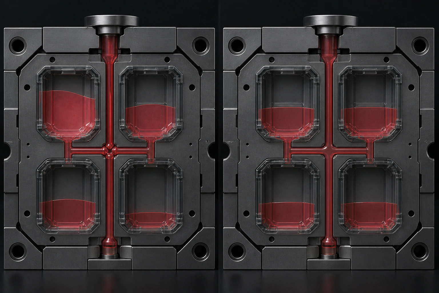
Raw cavity weights cannot be compared when one family-mold part is intentionally larger than another. Autodesk's family-mold guidance shows why equal-length, equal-diameter runners can overpack a smaller cavity while a larger cavity is still filling; the branches may need different restrictions so the parts finish filling together.[6]
For a family mold:
- compare each short shot with that cavity's own verified full-part mass or volume;
- report normalized fill fraction and gate-arrival sequence, not raw mass equality;
- judge each finished part against its own dimensional, cosmetic, and functional requirements;
- verify that the shared resin and achievable process window suit every part;
- document the economic trade: one lower-cost tool is accepting coupled process control across dissimilar parts.
There is no generally valid “2:1 part-volume ratio” that makes a family mold acceptable. Volume ratio is only one input; wall thickness, flow length, gate type, pressure demand, cooling, cosmetic requirements, and tolerance sensitivity can dominate the decision.
What to Request Before a Multi-Cavity Mold Ships
A useful acceptance package connects the digital prediction to the physical trial:
- cavity-numbered fill-time and pressure results from the released runner and gate design;
- the material grade and process settings used in the analysis;
- staged short-shot photographs with shot settings and a recorded fill rank;
- the full-part cavity-by-cavity weight dataset, including within-cavity variation;
- critical dimensions reported by cavity under stated conditioning and measurement conditions;
- the approved process window and the exact acceptance limits used;
- a revision record for every gate, runner, cooling, vent, or insert change.
Our mold-flow analysis overview describes evaluation of flow, temperature, pressure, and potential defects. Our inspection workflow separately identifies DFM review before production, and our multi-cavity versus family-mold guide provides public layout context. For a multi-cavity project, use the early review to agree on the evidence package: simulation predicts what should happen; numbered short shots and cavity-level data show what the delivered mold actually did.
Frequently Asked Questions
Does a naturally balanced runner guarantee equal cavity fill?
No. Equal nominal path length is a strong design starting point, but shear-induced temperature and viscosity gradients, gate differences, venting, cavity geometry, and cooling can still create imbalance.[2][3]
Why turn off hold pressure during a short-shot study?
The purpose is to observe the filling sequence before packing adds material to cavities that filled early. If packing remains active, it can reduce visible differences and make an imbalanced tool appear acceptable.
Is cavity weight enough to accept a multi-cavity mold?
No. Weight helps compare filling and packing by cavity, but acceptance must also cover the drawing's dimensions, cosmetics, function, and required capability. Similar weights do not prove identical shrinkage or material distribution.
What is a good cavity weight variation percentage?
There is no universal percentage. Define the metric and limit in the validation plan based on part requirements, scale capability, process variation, and risk. A supplier's house limit can be useful, but it is not automatically the correct product acceptance limit.
Can runner balance be fixed only with process settings?
Sometimes process changes reduce the measured imbalance, but published studies show that the result depends on material, runner layout, fill rate, and temperatures.[3][5] If the acceptable balance exists only at a narrow setting, the tool may not have a robust production window.
Conclusion
Multi cavity mold runner balancing is an evidence problem, not a visual judgment. First freeze the filling sequence with cavity-numbered staged short shots and no packing. Then restore the approved process and separate cavity-to-cavity mean differences from shot-to-shot variation within each cavity.
Keep the acceptance limits project-specific. A fixed sequence of fill percentages, a 30-shot sample, or a 1%/2% weight limit can be part of an agreed plan, but none is a universal standard. Correct the verified cause, rerun the same tests, and require the data before the mold ships. That is what turns “every cavity filled” into a defensible validation result.


-2.png)