-1.png)

A sink mark and a shrinkage void can be two visible states of the same volume-loss problem. As an injection-molded section cools, the center contracts after an outer skin has formed. If that skin moves inward, the surface sinks. If it is stiff enough to resist, the contraction can instead open an internal void. Autodesk describes this sink-to-void relationship directly. [1]
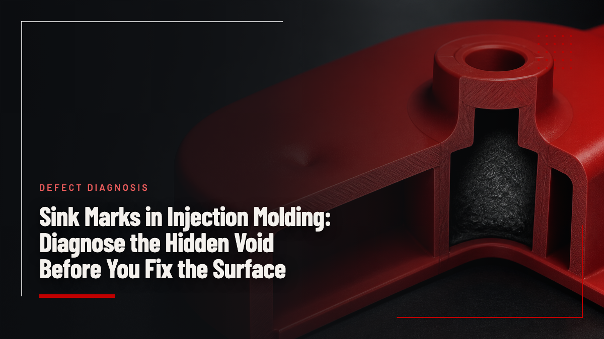
That creates a dangerous inspection trap. A process change can improve the surface without proving that the thick section became sound. More hold pressure, a different thermal profile, or a harder frozen skin may change where the contraction appears. For an opaque structural part, the correct question is not “Did the sink disappear?” It is “Where did the missing volume go, and did the interior remain intact?”
Distinguish Three Defects Before Adjusting the Process
The word “void” is often used for any internal opening, even when the mechanisms differ. Start by separating a surface sink, a shrinkage void, and a gas or moisture bubble.
| Defect | Typical evidence | Likely mechanism to test |
|---|---|---|
| Surface sink | Local depression, often opposite a rib, boss, fillet, or other thick transition | The cooling core contracts and pulls a compliant skin inward. |
| Shrinkage void | Internal opening concentrated near the center of a thick region; the outer surface may look acceptable | The frozen skin resists inward movement while inadequately compensated core shrinkage opens an internal cavity. |
| Gas or moisture bubble | Internal pocket that may correlate with wet material, degradation, trapped gas, a weld region, or the flow path rather than only the thickest core | Vapor or gas is enclosed in the melt; packing changes alone may not remove its source. |
BASF's engineering-thermoplastics troubleshooting guide says voids can form in high-volume-shrinkage regions when packing is inadequate and the edge layers have solidified enough to resist contraction. The guide also describes an immersion puncture check: whether water enters or gas escapes can help screen a vacuum void from a gas bubble. [2] Morphology is useful evidence, but it should be correlated with location, resin moisture, venting, processing history, and packing. A smooth or round opening by itself is not a universal root-cause test.
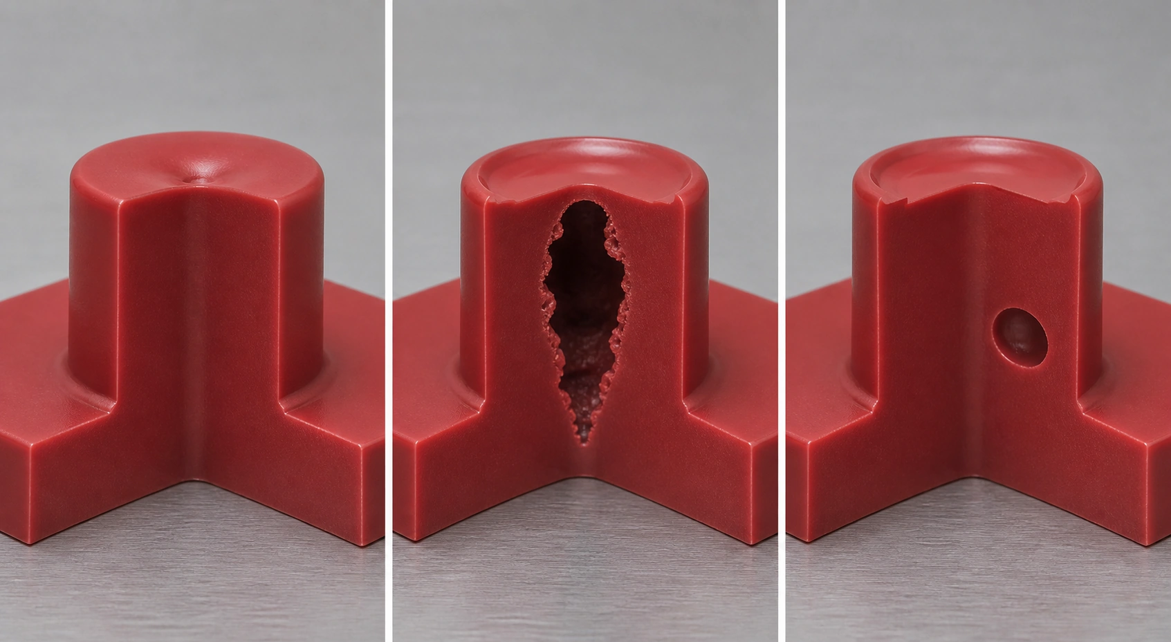
A Better Surface Can Hide a Worse Interior
Part weight is a valuable low-cost trend because packing additional material into a cavity usually raises weight until the gate no longer transmits pressure. RJG describes a gate-seal study that weighs parts at increasing hold times and selects a hold time beyond the minimum needed to prevent material from discharging back through the gate. [3]
The trend must be interpreted carefully:
-
If longer hold time raises part weight and reduces the sink, additional material is reaching the part. The section still needs confirmation if an internal void is a functional risk.
-
If the surface changes while weight does not rise beyond measurement noise, investigate whether the gate is already sealed, the scale lacks resolution, thermal skin behavior changed, or a hidden internal defect remains.
-
If weight continues to rise without dimensional stability, the process may be overpacking another region or the mold may be deflecting. More mass is not automatically better.
Part weight is therefore an indicator, not “the only proof” and not a substitute for viewing the interior. It is strongest when combined with a hold-time study, cavity-pressure data where available, and a section or validated CT scan.
Use a Section-First Diagnostic Protocol
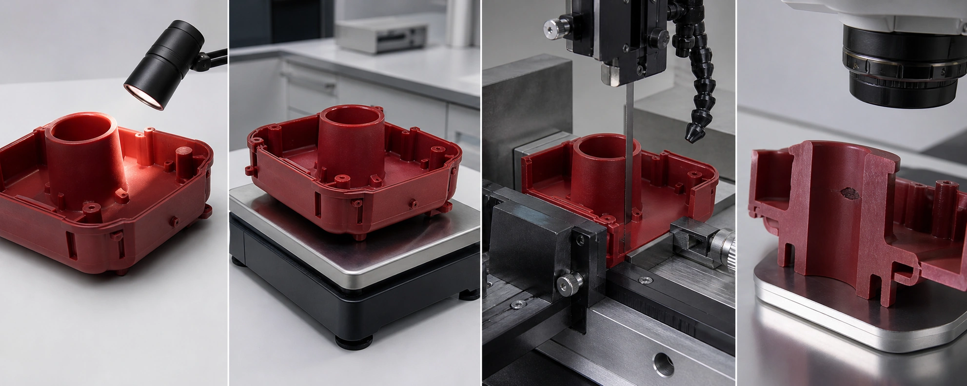
A controlled first-article study should look inside every functionally important thick feature, not just measure the dimensions already called out on the drawing.
-
Map the risk locations. Mark ribs, bosses, abrupt thickness transitions, insert surrounds, deep junctions, and thick areas separated from the gate by a thinner frozen path.
-
Preserve the molding condition. Record resin and lot, moisture condition where relevant, melt and steel temperatures, fill time, transfer position, cushion, hold profile, hold time, cooling time, cavity number, and part weight.
-
Choose section planes before cutting. A cut that misses the thermal center of a boss can falsely suggest the feature is sound. Photograph the intact part and reference the cut to drawing datums.
-
Prepare and inspect the cut. A rough saw surface can create tears that resemble defects. Use a preparation method and magnification suited to the required void size, then record void position, dimensions, and relation to the nominal wall.
-
Correlate, do not diagnose from shape alone. Compare the section with part weight, gate-seal behavior, moisture data, vent locations, and the change made between samples.
-
Repeat after meaningful changes. Re-section when a gate, rib, boss, cooling insert, material grade, or validated process window changes enough to alter shrinkage risk. Use a risk-based rule for routine repairs rather than sectioning after every maintenance action regardless of location.
For high-value parts or where destructive sectioning would consume scarce samples, industrial computed tomography (CT) can image internal structure without cutting. ASTM E1441-19(2026) explains CT's three-dimensional and cross-sectional capabilities, but it does not prescribe scan settings or acceptance criteria for a new part. Resolution, material thickness, artifact control, defect threshold, and correlation with a known section must therefore be validated for the application. [4]
Design Usually Sets the Ceiling
Sink marks and shrinkage voids concentrate where material volume is locally high and feeding becomes difficult. Autodesk lists thicker sections, ribs, bosses, internal fillets, high volumetric shrinkage, early gate freeze, low packing pressure, and short packing or cooling time among the relevant causes. Its remedies include reducing thick sections, relocating the gate toward the problem region, improving the runner, and optimizing packing. [1]
Remove the Material Accumulation
Coring out a thick boss, reducing an abrupt transition, or replacing solid thickness with appropriately designed ribs attacks the volume that must cool and shrink. This is usually more robust than compensating indefinitely with pressure.
Rib ratios must remain material-, height-, surface-, and application-specific. The BASF guide illustrates a rib connection of about 0.5 times nominal wall for a particular glass-fiber-reinforced Ultramid example. [2] It should not be promoted as a universal ratio for every resin, texture, polish level, or structural requirement. Treat supplier guidance as a starting point, then evaluate sink visibility and strength on the actual geometry.
For a deep rib or boss, the limit can be set by the forming steel rather than the nominal plastic ratio: review insert aspect ratio, unsupported steel depth, machining or EDM access, cooling, venting, polish access, and ejection. On a high-polish or primary appearance surface, set the rib or boss junction from the permitted read-through and validated cosmetic standard; a ratio acceptable on a hidden face may still be unacceptable there.
Keep the Pressure Path Open
Packing can compensate shrinkage only while a molten path connects the screw to the contracting region. If the gate or a thin upstream section freezes first, increasing machine hold time cannot transmit more material to the thick core.
BASF's cooling-time guidance makes the feed-system trade-off explicit: if the runner or gate freezes too early, effective holding pressure can no longer be applied; if it freezes excessively late, the cycle is unnecessarily extended. [5] Gate size and location are therefore dimensional and internal-quality decisions, not merely fill decisions.
Apply Process Levers in an Evidence-Based Order
Once the design and feed path are understood, use a controlled sequence:
-
Stabilize filling first. Confirm a consistent fill-only state, transfer position, cushion, melt condition, and cavity-to-cavity balance. Otherwise, a packing study is built on a moving input.
-
Determine effective hold time. Increase hold time in steps and plot part weight by cavity. The plateau is evidence of gate-seal behavior under that process, not a universal cycle-time value. [3]
-
Optimize the hold-pressure profile. Increase compensation within flash, clamp-force, mold-deflection, residual-stress, and dimensional limits. Record cavity response rather than relying only on hydraulic setpoints.
-
Review steel temperature and cooling balance. Local temperature changes alter frozen-skin development, crystallization, cycle time, and where shrinkage appears. A surface improvement must be followed by interior verification.
-
Change the feed system or geometry when the process reaches its limit. A larger or relocated gate, a cored feature, a thinner rib junction, or revised cooling may be the real correction.
A recent peer-reviewed study of a specific thick PA66-GF30 gauge plate found wall-thickness variation to be the primary sink-void driver in that part; structural modifications that improved thickness uniformity reduced predicted and sectioned void risk. Its optimized temperatures, pressures, and times belong to that material, tool, and experiment, but the result supports a broader lesson: geometry can dominate what process tuning is able to recover. [6]
Reserve Advanced Options for the Right Constraint
Gas assist, microcellular molding, local conformal cooling, and a lower-shrink or mineral-filled grade can be valid options when a thick section cannot be removed. They change equipment, tooling, surface, material properties, or validation requirements, so they should not be treated as interchangeable quick fixes.
Before choosing one, define why conventional coring, rib redesign, gate access, and cooling cannot meet the requirement. Then validate internal structure, surface class, mechanical behavior, and dimensions in the final process and material state.
Our common molding defects guide and plastic injection molding service provide public troubleshooting and manufacturing context. Our inspection workflow lists DFM and tolerance/cosmetic review, incoming-material inspection, a full-dimensional report after T1, in-process checks, and a pre-shipment report. For a sink- or void-critical project, add the section planes, permitted internal-discontinuity criteria, part-weight study, and any CT procedure to the project specification before T1. Those internal-inspection steps are project-specific recommendations; the public page does not list plastic-part sectioning or CT as a standard deliverable.
Frequently Asked Questions
Can increasing hold pressure eliminate a sink mark?
It may reduce a sink if pressure can still reach the contracting region. Confirm gate-seal behavior, part-weight response, flash and stress limits, and the internal section. A better surface does not by itself prove that a hidden void is gone.
How can a shrinkage void be distinguished from a gas bubble?
Use location, section morphology, a controlled immersion or gas-release screen where suitable, resin-moisture data, vent and degradation history, and packing response together. CT or a prepared destructive section can reveal the interior, but no single shape rule identifies every mechanism.
Does a stable part weight prove there are no voids?
No. A weight plateau is primarily evidence about gate seal and the amount of material retained under that process. It cannot show how the mass is distributed inside the part or whether a local void remains.
When should a part be sectioned?
At minimum, section functionally critical thick features during first-article validation and after changes that materially affect geometry, gating, cooling, resin, or the approved process window. The frequency should reflect the consequence of an undetected void and the ability of another validated inspection method to detect it.
Conclusion
The safest response to sink marks in injection molding is to inspect the interior before declaring the surface fixed. Use part-weight and gate-seal trends to understand whether added material reaches the cavity, then confirm thick regions by prepared sectioning or validated CT. Correct material accumulation and pressure-path limits before pushing hold pressure toward its ceiling. When the drawing, DFM, T1 report, section plan, and acceptance criteria describe the same risk, a cosmetic improvement is far less likely to hide a structural defect.
Sources
[1] Autodesk Moldflow Adviser: Troubleshooting Sink Marks and Voids
[2] BASF: Injection-Molding Problems in Engineering Thermoplastics — Causes and Solutions
[3] RJG: Seeing Gate Discharge With Sensors — Gate-Seal Study by Part Weight
[4] ASTM International: ASTM E1441-19(2026) — Standard Guide for Computed Tomography