POM is often described as a "2% shrink material." That shorthand is useful for an early conversation and dangerous as a tooling instruction. Delrin's molding guide gives a typical mold-shrinkage range of about 1.7–2.2% for many unfilled grades, but actual dimensions also depend on grade, wall thickness, flow orientation, gate design, mold temperature, packing, and when the part is measured. Reinforced and toughened grades can behave very differently. [1]

Dimensional control in POM injection molding does not come from finding one perfect percentage. It comes from defining a complete condition: the exact commercial grade, the cavity and flow direction, the molding window, the post-molding state, and which critical dimensions remain safe to correct after T1.
POM Has More Than One Shrinkage Event
ISO 294-4 distinguishes molding shrinkage from post-molding shrinkage and measures change both parallel and normal to flow. It also excludes dimensional change caused by moisture uptake from the molding-shrinkage definition. ASTM D955 provides molding-shrinkage measurements at defined time points including 24 and 48 hours. [2][3] Those distinctions matter because a part can leave the press inside tolerance, move during the first day, and continue changing later in service.
Mold Shrinkage
Mold shrinkage is the dimensional difference between the mold cavity and the freely molded part after cooling and conditioning under the stated test method. It is the value most commonly associated with the shrinkage number on a material data sheet. It is not a universal material constant: specimen geometry, thickness, flow direction, gate, mold temperature, pressure, and measurement timing affect the reported result.
Post-Mold Shrinkage
Post-mold shrinkage is the additional change after the initial molding-shrinkage measurement. Delrin describes it as continued crystallization and stress relaxation after the first 24 hours, with magnitude dependent on time and temperature. Celanese's Hostaform manual treats mold shrinkage, after-shrinkage, and total shrinkage as separate quantities. [1][4]
The useful engineering target is total dimensional behavior under the project's agreed condition—not the first dimension that comes off the machine.
The High-Mold-Temperature Paradox
A warmer mold usually allows more crystallization before ejection. The immediate molded part may therefore show greater mold shrinkage, while later post-mold shrinkage is reduced. A colder mold can produce a part that initially appears closer to nominal but retains more unfinished crystallization and internal stress, increasing later dimensional drift. Both Delrin and Hostaform guidance describe this trade-off. [1][4]
This is why lowering mold temperature to rescue an oversize dimension can be a false win. The process may move the part into tolerance at the first measurement while making its later stability worse. For precision parts, the mold temperature should be selected within the resin supplier's window for the intended dimensional and service-temperature requirement, then held consistently during validation and production.
| Variable | Typical dimensional effect | Control decision |
|---|---|---|
| Material grade | Changes shrinkage magnitude, toughness, crystallization and filler anisotropy | Specify the exact commercial grade and approved alternates before tooling |
| Mold temperature | Higher temperature can increase immediate shrinkage but reduce later shrinkage | Select for total dimensional stability, not only the first measurement |
| Packing to gate seal | Insufficient packing generally increases shrinkage and variation | Establish gate-seal behavior and a robust hold window |
| Wall thickness and flow direction | Create local and directional differences in shrinkage | Review critical dimensions relative to predicted flow and gate location |
| Measurement time and constraint | Changes the reported result even when the molded part is identical | Define time, temperature, humidity and free or assembled state |
Supplier Processing References Are Starting Windows, Not Setup Sheets
Published supplier conditions help define a defensible first trial, but they do not replace the selected grade's current datasheet, the molding-machine limits, or a project-specific validation window. Delrin's 2024 molding guide gives the following reference conditions for its product family. [1]
| Supplier reference | Published starting point | Boundary for use |
|---|---|---|
| Melt temperature, standard grades | 215 ± 5°C | Do not transfer to every acetal producer or specialty grade |
| Melt temperature, low-emission and toughened grades | 205 ± 5°C | Confirm the exact commercial grade and current guide |
| Mold temperature, standard grades | 80–100°C; up to 120°C may be necessary for some high-precision applications | Select from total dimensional behavior, surface, cycle, and service condition |
| Hold pressure | 60–110 MPa, depending on grade | Establish gate seal and avoid treating one value as a universal setpoint |
| Screw peripheral speed | 0.3 m/s or lower | Convert to machine rpm from the actual screw diameter and supplier guidance |
Grade-specific shrinkage data show why a family average cannot be used as a mold allowance. In Delrin's 2024 product reference guide, ISO 294 test values differ materially among unfilled, reinforced, and toughened grades. [6]
| Delrin grade in supplier table | Mold shrinkage parallel to flow | Mold shrinkage normal to flow |
|---|---|---|
| 500P NC010, unfilled | 2.0% | 1.9% |
| 510GR NC000, reinforced | 1.0% | 1.4% |
| 525GR NC000, reinforced | 0.4% | 1.2% |
| 100ST NC010, toughened | 0.8% | 1.1% |
These are supplier test-specimen results, not correction factors for a production cavity. Part geometry, gate location, pressure history, mold temperature, direction, and measurement condition still have to be represented in the DFM assumption and verified at T1.
A Measurement Protocol That Produces Comparable Data
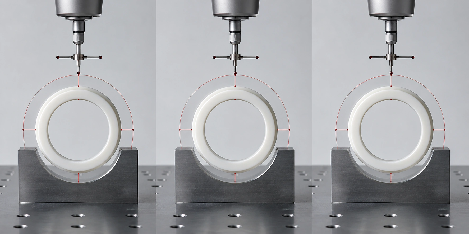
A dimensional report is only useful when its measurement condition is reproducible. For critical POM parts, define the protocol before T1:
-
Identify the exact resin producer, grade, color and reinforcement level used for the trial.
-
Record the stabilized molding conditions, including mold temperature and the packing or hold settings used through gate seal.
-
Specify the first measurement time—24 or 48 hours, for example—rather than reporting "after molding" without a clock.
-
Control and record measurement temperature and humidity, especially when comparing results from different sites.
-
State whether the part is measured freely or in an assembly fixture. A flexible feature can report a different dimension when constrained.
-
For dimensions sensitive to long-term stability or elevated service temperature, add a later measurement point or a project-specific conditioning study.
A 30-part sample and Cp/Cpk analysis may be appropriate for a capability study, but it is not a universal POM requirement and it does not rescue an unstable process. Sample size, measurement-system capability, cavity strategy, and statistical acceptance should come from the project's quality plan.
Build Correction Direction Into the Mold
A shrinkage estimate is still an estimate. The mold should therefore be made correction-safe on the critical dimensions identified during drawing review. For an outside dimension formed by a cavity, the steel can be left so the feature is initially conservative and can be enlarged by removing steel. For an inside dimension formed by a core, the correction direction is the opposite. The exact steel-safe decision must be made dimension by dimension; applying a blanket offset to the entire model can move one feature in the correct direction and another in the wrong direction.
This matters more with POM because an error in a relatively large shrinkage allowance becomes a visible steel error. A 0.2 percentage-point difference across a 100 mm feature is already 0.2 mm before local flow, pressure and geometry effects are considered.
Gate Location Sets the Shrinkage Direction
ISO 294-4 measures shrinkage both parallel and normal to flow because semi-crystalline materials can be direction-dependent. Reinforcement makes that difference more pronounced: fibers align with flow and constrain shrinkage differently along and across their orientation. The gate is therefore part of the dimensional strategy. Moving it changes the pressure path, orientation field, weld-line location, and the direction in which a critical feature experiences shrinkage.
For a dimensionally critical part, review the gate and critical-dimension map together. A molding simulation can estimate flow and orientation, but grade-specific supplier data and T1 measurement are still required to correct the tool.
POM Annealing Is a Defined Production State, Not a Default Repair
Annealing can accelerate stress relaxation and post-mold dimensional change, but it adds another thermal cycle and can reveal or create distortion. Delrin recommends it only for selected tight-tolerance or elevated-temperature applications, using a grade-specific time and temperature procedure. The same procedure should not be copied to another producer's POM, and an extrusion annealing rule should not be applied to an injection-molded part. [1]
If annealing is part of the delivered condition, validate and measure the part after annealing. If it is not part of the production route, do not anneal a few samples merely to make a dimensional report look stable. A warm-mold process that allows more crystallization before ejection is often a more repeatable starting point than cold molding followed by an unplanned secondary operation.
Two Processing Risks That Need Precise Language
Overheating and Cross-Contamination
POM can decompose when melt temperature or residence time is excessive, when material stagnates in the barrel, or when it is contaminated by incompatible acidic polymers such as PVC. Formaldehyde is a principal decomposition product, so ventilation, temperature control, purge and shutdown practice are safety as well as quality issues. The correct limit and purge procedure must come from the exact grade supplier; "never use a machine that once ran PVC" is too broad, but casual purging between PVC and POM is not an acceptable control. [1][5]
Copper Alloys
Molten POM can degrade faster during prolonged contact with copper, brass or bronze in hot, stagnant regions of the injection unit. That warning does not make every copper-alloy mold component or copper insert incompatible. Delrin's molding guidance distinguishes prolonged molten contact from ordinary mold components where the resin solidifies and leaves each cycle. For insert molding, review the exact grade, insert geometry, melt-contact time and supplier guidance instead of applying a blanket prohibition. [1]
What to Put Into the DFM and T1 Package
For a POM program, the useful inputs are the exact grade, expected service temperature, assembly constraint, critical dimensions, measurement timing, and any required post-molding condition. The useful outputs are the proposed shrinkage assumptions by direction, gate and flow review, steel-safe plan, recorded molding condition, and a dimensional report generated at the agreed time.
Our plastic injection molding service and manufacturing materials overview identify the public starting points for discussing POM grade and manufacturability. Our inspection workflow describes incoming-material, T1 dimensional, in-process, and pre-shipment checkpoints. Use those checkpoints to agree on the exact grade and measurement condition before judging a dimension; project-specific tests and acceptance limits still need to be written into the handoff.
Frequently Asked Questions
What is the typical shrinkage of POM?
Many unfilled Delrin grades are commonly described in the 1.7–2.2% mold-shrinkage range, but no single percentage covers all POM. Reinforcement, grade, wall thickness, flow direction, mold temperature, packing and test geometry can move the result.
When should a POM part be measured?
Use the timing required by the drawing, customer specification or agreed validation plan. ASTM D955 includes 24- and 48-hour measurements; a critical project may add a later stability point. The report should always state the timing and conditioning.
Does a higher mold temperature reduce POM shrinkage?
It may increase immediate mold shrinkage while reducing later post-mold shrinkage. The engineering decision should target total dimensional stability, not only the first dimension after ejection.
Should all precision POM parts be annealed?
No. Annealing is a project- and grade-specific secondary operation. Use it only when the delivered condition, service temperature and tolerance requirement justify it, and validate the part in that final state.
Conclusion
POM dimensional control is a chain of defined conditions. Replace the single "2%" assumption with a grade-specific shrinkage basis; separate mold shrinkage from post-mold shrinkage; select mold temperature and packing for total stability; measure at an agreed time and state; and leave the critical steel correctable. When those decisions are documented before tooling, POM becomes predictable enough for gears, latches, sliding components, and other tolerance-sensitive parts.
Sources
[1] Delrin: Technical Molding Guide, 2024
[2] ISO 294-4:2018—Determination of moulding shrinkage
[3] ASTM D955-21—Standard Test Method of Measuring Shrinkage
[4] Celanese: Hostaform Product Manual
[5] Polymer Degradation and Stability: Processing, ageing and recycling of POM