

A burn mark at the end of fill looks like a venting problem, but appearance alone is not proof. The same part can burn because air has nowhere to escape, because the melt is degrading, or because the process is pushing an otherwise workable vent beyond its capacity. Cutting a deeper groove before separating those causes can trade one defect for another: the burn disappears, then flash starts at the parting line.
Effective injection mold venting begins with diagnosis. The job is to determine where gas is trapped, why it is there, whether the escape path is undersized or blocked, and whether the material is generating more gas than the original venting plan anticipated. Only then should steel be changed.
First, Prove That Trapped Gas Is Involved
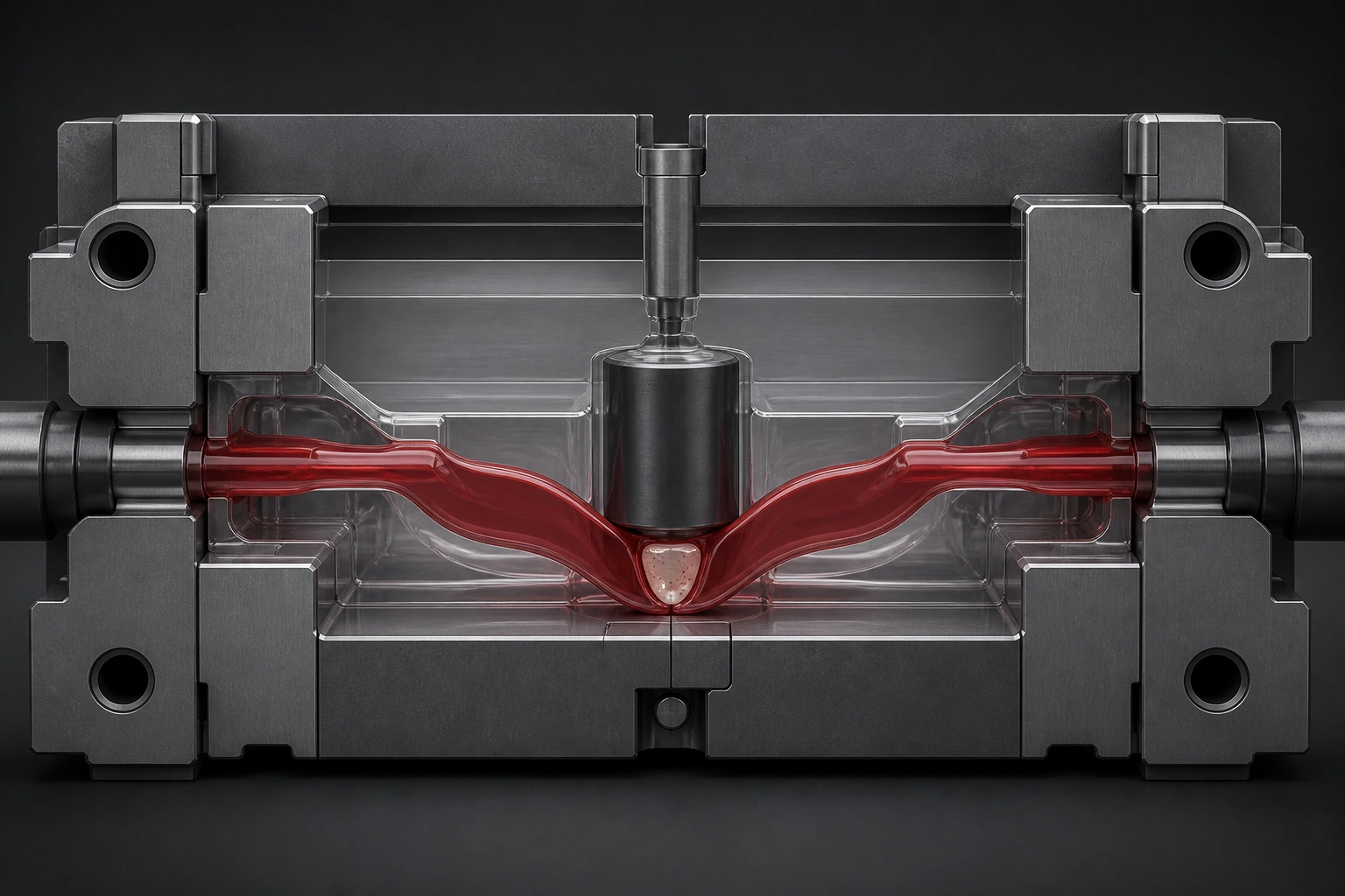
Autodesk Moldflow identifies converging flow fronts, hesitation, racetracking, unbalanced flow paths, and inadequate venting as common causes of air traps. When air is compressed ahead of the melt, it can resist filling, increase required pressure, blemish the surface, or heat enough to burn the polymer. The useful diagnostic question is therefore not simply "Is there a burn mark?" but "Does the location and timing of the defect match a plausible trapped-gas path?" [1][2]
| Observed pattern | What it suggests | What to verify next |
|---|---|---|
| Defect repeats at the same end-of-fill or weld location | A geometric air trap or missing vent is likely | Short-shot progression, fill-time result, gate location, blind ribs and vent location |
| Defect moves or varies strongly from shot to shot | Process or material stability may be contributing | Shot size, transfer position, melt temperature, residence time, material condition and check-ring consistency |
| Tool ran cleanly, then burns increased over a production run | Vent restriction or volatile deposit is plausible | Inspect and clean vents, ejector clearances and runner-end escape paths; compare before/after condition |
| One branch or a few cavities repeatedly fill late | Runner air or flow imbalance may be feeding a local gas problem | Run staged short shots by cavity; inspect branch ends, cold wells and runner vents |
Use Process Changes as Controlled Tests, Not as Proof
Injection speed is often used as a diagnostic lever, but it does not have one universal direction. Slowing the melt may reduce compression heating when the escape path is poor. In a hesitation-driven or converging-flow problem, however, a slower front can worsen freezing and allow more air to be trapped. Autodesk therefore recommends reading the air-trap result together with fill time and the actual flow-front history rather than applying "slower is better" as a rule. [2]
A small, controlled reduction in clamp force can also be informative if the mold remains safely closed and does not flash. If the defect improves, excessive clamping or a restricted parting-line vent deserves investigation. The result is indicative, not conclusive: clamp force changes the entire mold interface and cannot identify the exact blocked vent by itself.
The strongest confirmation combines several observations: a repeatable air-trap location, a matching last-to-fill or convergence pattern, a defect response consistent with gas compression, and a physical escape path that is missing, undersized, damaged, or contaminated.
Vent Depth Is Resin- and Grade-Specific
There is no defensible universal vent depth for every thermoplastic. In a peer-reviewed study that combined Moldflow prediction with a vented additively manufactured tool, the authors discussed typical vent channels about 0.01–0.05 mm deep and 1.5–6 mm wide, depending on material grade. For Delrin 500P, the study used the resin manufacturer's recommended 0.02 mm depth. [3]
A Celanese Celcon POM processing guide gives a different grade-family reference: a maximum vent depth of 0.0254 mm with a width of about 3.175–6.35 mm, followed by a deeper relief after a short sealing land. It recommends venting the point farthest from the gate as well as runner, weld-line, and known gas-trap areas. [4] These values are useful examples precisely because they are material-specific; they should not be copied to ABS, PC, PA, filled grades, or another POM without checking that supplier's data.
The right sequence is simple: identify the exact commercial grade, read the supplier's processing guide, start within its vent range, then confirm the result under the intended process window. Filler level, melt flow, flame-retardant package, surface requirement, and local shear history can all change how much clearance is safe before flash begins.
Venting Capacity Is More Than One Groove's Depth
A vent is a flow path for gas. Its capacity depends on the entrance clearance, total vent length, distribution around the cavity, relief geometry, surface condition, and where the gas is generated. Deepening one vent increases local clearance, but it also increases flash risk. When air load is high, adding well-distributed vent length or a separate runner escape path may be more effective than making one opening deeper.
This distinction matters with materials that release volatiles or with processes that use additives, flame-retardant packages, colorants, or excessive residence time. The tool may have enough clearance to pass ordinary cavity air during early cycles but lose capacity as condensable material coats the vent surfaces.
Why Mold Vents Lose Effectiveness
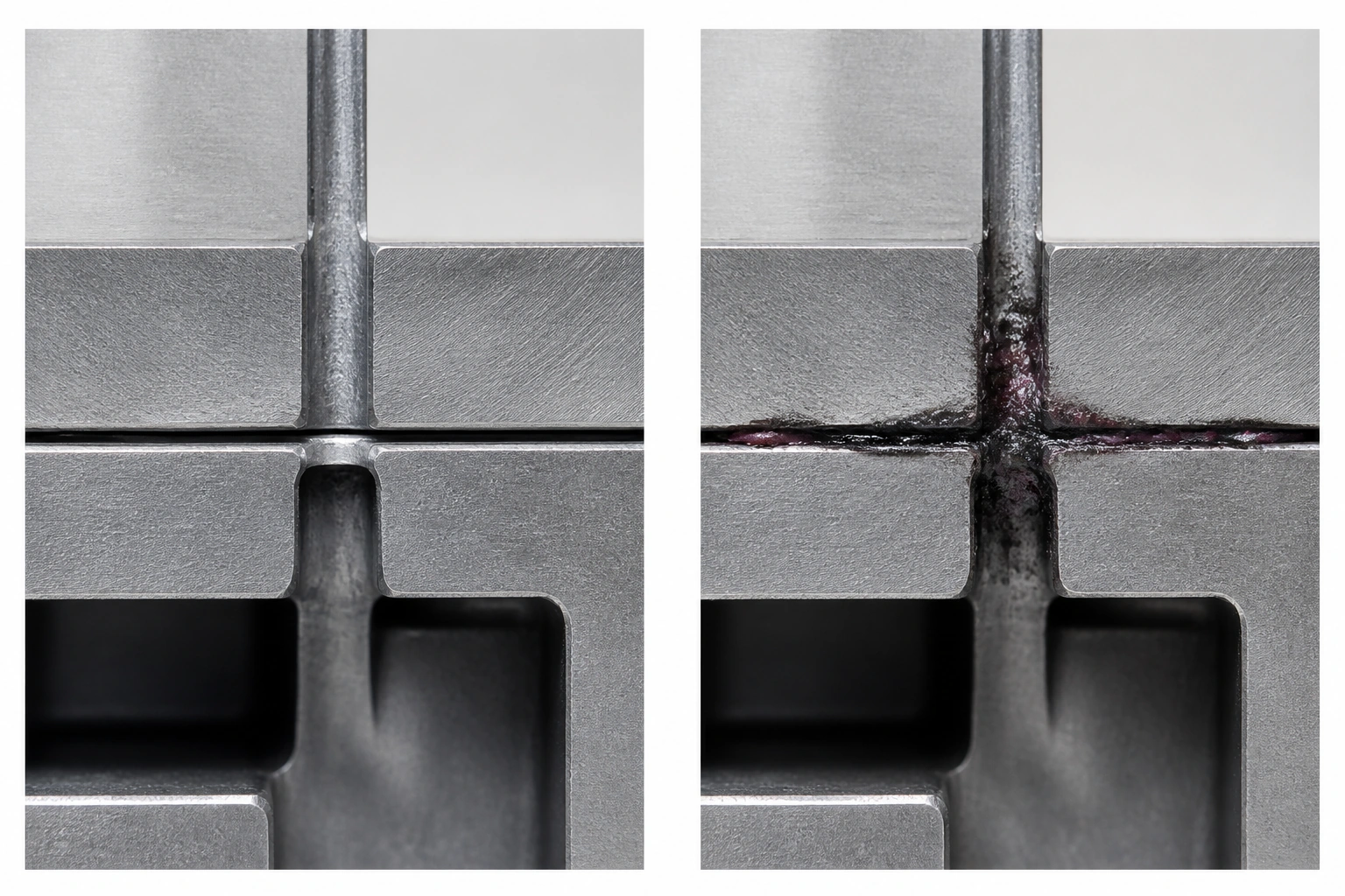
Vent restriction is not always caused by steel dimensions. Research on vent-clogging monitoring found that low-molecular-weight substances can vaporize from the melt, then condense and deposit around ejector-pin clearances and venting paths. As deposits accumulate over repeated cycles, flow resistance rises and the vent can eventually clog, producing molding defects. [5]
Maintenance should therefore distinguish two conditions:
-
A vent that is dimensionally intact but restricted by plate-out, residue, corrosion product, or contamination.
-
A vent whose geometry changed after parting-line repair, welding, grinding, polishing, or flash correction.
Both require a controlled baseline. Record vent locations and intended dimensions at tool acceptance; define a cleaning method compatible with the mold material and surface; inspect vents when burn marks trend upward; and recheck critical vent geometry after work on the parting line. The record is more valuable than a generic instruction to "clean vents regularly" because it shows what the vent was supposed to be.
Check Runner Venting Before Modifying Cavity Vents
Air in the runner system must leave before the melt can reach the cavity cleanly. If it is driven into the cavity instead, a local short shot or burn can look like a cavity-only problem. Runner ends, cold-slug wells, sharp direction changes, and branch ends are logical places to evaluate for trapped air. Celanese's POM guidance explicitly includes runner venting among the recommended locations. [4]
In a multi-cavity tool, staged short shots are especially useful. Lay out every cavity by number and compare the fill sequence. If the same branch always fills late, inspect runner balance and runner air management before modifying every cavity vent. A process can contain both problems, and fixing only the cavity symptom may leave the branch-to-branch cause untouched.
Plan Vent Locations Before Steel Is Cut
Air-trap plots are most useful as a design input. They should be reviewed with fill time, predicted weld lines, gate position, wall-thickness transitions, deep bosses, blind ribs, and the actual path gas must take to reach the parting line. Last-to-fill is important, but it is not the only location where air can be isolated; two fronts can surround air earlier in the fill sequence.
At the DFM stage, mark the expected end-of-fill and convergence zones, assign a venting method to each, and identify any area that cannot reach a conventional parting-line vent. This is the point to consider ejector-pin clearances, inserts, overflow features, or a gate adjustment. Adding a vent to hardened steel after T1 is possible, but it is rarely cheaper than assigning the path before machining.
A Practical Venting Handoff
For a new mold, a useful handoff includes the material grade and supplier vent recommendation, the predicted air-trap and weld-line locations, the actual vent map, the acceptance dimensions, and the maintenance checkpoints. For an existing mold, add defect photographs by cavity and cycle stage, a staged short-shot study, and before/after vent inspection results.
Our plastic injection molding service and DFM guide provide public manufacturing and design context. Our inspection workflow lists DFM review, incoming-material checks, T1 dimensional reporting, in-process inspection, and final inspection. Bring vent locations and resin-specific limits into that DFM and T1 discussion so the decision remains connected to the material and tool record instead of becoming an undocumented press-side adjustment.
Frequently Asked Questions
What defects can poor injection mold venting cause?
Poor venting can contribute to burn marks, short shots, incomplete packing, surface blemishes, high fill pressure, weld-line weakness, and inconsistent filling. None of these defects is unique to venting, so the location and flow history must be checked before steel is changed.
Should a burn mark always be fixed by cutting a deeper vent?
Not necessarily. First determine whether the existing vent is blocked, whether the material is degrading, whether the gas originates in the runner, and whether the proposed depth is safe for the exact resin grade. A deeper vent may replace a burn mark with flash.
How often should mold vents be cleaned?
There is no universal cycle count. Set the interval from the resin, additive package, observed deposit rate, production volume, and defect trend. High-outgassing or flame-retardant materials may need more frequent inspection than a clean-running unfilled grade.
Can Moldflow determine the final vent design automatically?
Simulation can identify likely trapped-air and last-to-fill regions, but final vent dimensions still require resin-supplier guidance, tooling judgment, and confirmation during mold trials.
Conclusion
Reliable injection mold venting is a diagnosis-and-control problem, not a single depth value. Confirm that the defect pattern matches trapped gas, use the exact resin supplier's vent guidance, provide enough distributed escape capacity in both runner and cavity, and preserve the original vent design in the tool record. When vent performance changes, inspect deposits and maintenance history before cutting more steel.
Sources
[1] Autodesk Moldflow 2026: Fill or Flow Results—Air Traps
[2] Autodesk Fusion: Air Traps Result
[3] International Journal of Advanced Manufacturing Technology: Embedded venting and air-trap validation
[4] Celanese: Celcon POM Processing and Troubleshooting Guide
[5] Journal of Manufacturing Processes: Development of vent clogging monitoring methods


-2.png)