-1.png)

Choosing a recognized mold steel does not guarantee a stable insert. Its incoming condition, machining history, heat-treatment cycle, geometry, and finishing sequence all influence the dimensions and properties delivered to the mold.
Heat treatment also creates a design tradeoff. Higher hardness can improve resistance to wear and plastic deformation, but the optimum condition still depends on steel grade, mold geometry, molding conditions, and toughness requirements. Uddeholm's plastic-mold guidance places normal working hardness for through-hardened mold steels across a broad 46-60 HRC range, not at one universal target. [1] A mold steel heat treatment specification should therefore begin with the service problem and exact steel, then define what will be measured before and after the furnace cycle.
Set Hardness From the Service Condition, Not Resin Name Alone
Resin family is only a starting point. Production quantity, glass or mineral reinforcement, pigment and additive package, cavity pressure, required surface finish, corrosion exposure, weld-repair risk, section size, and failure consequence can change the appropriate steel and hardness.
| Mold condition | Useful starting strategy | Boundary to document |
|---|---|---|
| Prototype or bridge production with modest wear | A machinable pre-hardened mold steel may avoid post-machining hardening | Confirm delivered hardness, local section properties, polish requirement, and expected shot count |
| Longer production or abrasive compounds | Consider a through-hardened grade and a higher wear-resistance target | Balance wear against toughness, cracking risk, geometry, and repairability |
| Corrosive resin by-products, additives, or operating environment | Select a corrosion-resistant mold-steel system | Surface treatment cannot compensate for an unsuitable substrate or poor maintenance |
| Sliding or localized wear features | Evaluate a dedicated insert, wear component, nitriding, or coating | Check support, contact stress, treatment depth or coating thickness, and repair route |
| High-polish optical or cosmetic surfaces | Prioritize steel cleanliness, homogeneity, hardness consistency, heat treatment, and polishing practice | A hardness number alone does not establish polishability |
Uddeholm distinguishes pre-hardened steels, commonly supplied at about 270-400 HB, from through-hardened steels used where longer runs, abrasive molding compounds, and higher pressures demand more wear resistance. It also identifies cleanliness, homogeneity, hardness, and heat treatment as contributors to polishability. [1] These are selection relationships, not automatic acceptance limits.
The purchase specification should name the exact grade, incoming condition, target hardness range and test method, test locations, governing datasheet, and surface-treatment plan. "Harden as much as possible" is not a specification. Excessive hardness can reduce the toughness margin at sharp transitions, thin sections, or repaired areas.
Put Stress Relief Before the Dimensions Become Expensive
A robust sequence for a heat-treated insert is usually:
- Verify steel identity, heat number, incoming condition, and stock allowance.
- Rough-machine the insert while leaving documented stock on critical surfaces.
- Stress-relieve when the grade, section change, machining removal, and dimensional risk justify it.
- Semi-finish and re-establish datums after any movement.
- Harden and temper to the grade-specific procedure.
- Measure the defined datum-and-feature map again.
- Grind, EDM, polish, texture, or coat in the planned order.
- Complete final hardness, dimensional, surface, and fit verification.
Uddeholm recommends rough machining followed by stress relieving and semi-finishing before hardening for high-precision tooling. It explains that rough machining releases residual stresses and creates new ones; if the part is fully finished first, stress relief can move already-critical dimensions. [2] Stress relief is not a cure for poor stock geometry, severe asymmetry, or an unsuitable heat-treatment fixture. Its value is that movement can occur while recoverable machining stock remains.
Stress-relief and hardening parameters must come from the selected steel, prior condition, and governing section. A temperature copied between grades can change hardness or microstructure; the current producer datasheet should govern.
Vacuum furnaces are useful where a protected environment is required. They can prevent oxidation and decarburization when the process is controlled correctly, but furnace atmosphere alone does not guarantee the least distortion. [2] Heating uniformity, support, section transitions, transformation behavior, quench severity, and starting stress state remain relevant.
Treat Distortion as a Measured Output
Dimensional change during mold steel heat treatment is normal; the engineering task is to bound and accommodate it. ASM identifies tool design, initial material condition, machining, and heat treatment as contributors to changes in shape and size, including changes that occur after the main cycle. [3] Uddeholm separates three mechanisms: stresses from heating and cooling, stresses released from machining, and dimensional change associated with microstructural transformation. [2]
Reduce risk before specifying a blanket allowance:
- Keep section changes gradual and add radii where the mold function permits.
- Use balanced geometry and machining removal when possible.
- Give the heat treater the insert drawing, critical faces, sensitive thin sections, blind holes, and required support orientation.
- Agree where stock will remain for grinding and where additional stock would alter the heat response or finished function.
- Avoid defining critical dimensions from unfinished or unstable reference surfaces.
- Separate expected size change from unacceptable bow, twist, taper, cracking, or local collapse.
Slower and more uniform cooling tends to reduce thermal gradients, but the quench must still be fast enough for the required microstructure. [2] "Use the slowest quench" is therefore incomplete. The acceptable method is the least severe validated quench that still achieves the grade's required transformation and properties throughout the governing section.
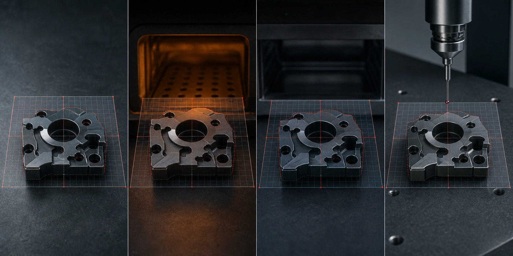
A pre/post measurement map makes the result actionable. At minimum, identify:
- the datum structure and measurement temperature;
- size, form, and orientation at repeatable locations;
- critical bores, pockets, shutoffs, and locating faces;
- measurement method, finishing stock, and correctable movement.
Measure after semi-finishing and before hardening, then repeat the same setup after hardening and tempering. A single overall dimension cannot distinguish uniform growth from bow or taper. For a long insert, a grid or section-by-section map is more informative than one center reading.
Tempering and Subzero Treatment Need Grade-Specific Logic
Tempering is part of hardening, not an optional follow-up. Uddeholm recommends at least double tempering for tool steels: the first cycle tempers newly formed martensite, while the second also tempers martensite formed from retained austenite during cooling after the first cycle. It recommends a third temper for large plastic molds and applications demanding especially high dimensional stability. [2]
If a grade that requires a second temper receives only the first cycle, retained austenite can transform as the tool cools and leave newly formed martensite untempered. The possible consequence is later hardness or dimensional change rather than a reliably finished condition. That is a conditional failure mechanism, not proof that every single-tempered insert is defective; the selected steel's current datasheet and recorded cycle govern. [2]
That guidance does not justify an automatic "three tempers for every insert" rule. The steel grade, hardening temperature, target hardness, section size, and producer procedure determine the cycles. Record actual temperatures and times rather than accepting "double tempered" without traceability.
Subzero treatment can reduce retained austenite for some grades. Uddeholm notes that high-temperature tempering alone may be adequate, while the highest stability may use subzero treatment with high-temperature tempering. [2] Specify cryogenic processing only when supported by the grade datasheet and stability requirement.
Nitriding vs PVD Starts With the Substrate
Nitriding diffuses nitrogen into the steel surface to create a hardened case. It can improve resistance to wear, erosion, and indentation, but the allowable temperature and case depth are grade- and application-specific. Uddeholm warns that nitriding can reduce corrosion resistance in some high-chromium steels, produces a surface that is difficult to machine or weld, and can create excessive layer build-up at sharp corners. The substrate should be tempered above the planned nitriding temperature. [2]
PVD applies a thin, adherent coating rather than creating the same type of diffusion case. Oerlikon describes typical PVD coatings as only a few thousandths of a millimeter thick and applied at roughly 150-500 degrees C, depending on the system. [4] Its coating guidance requires the prior heat treatment to tolerate the coating temperature without unacceptable hardness loss or distortion. [5]
The practical nitriding vs PVD decision should compare the wear mechanism, substrate hardness and support, required treated depth, dimensional tolerance, surface finish, operating temperature, corrosion exposure, stripping or repair method, and treatment temperature. Neither treatment repairs a soft, cracked, poorly supported, or dimensionally incorrect insert. Apply nitriding or coating after the mold geometry and molding performance are approved when later machining would damage the treated surface. [1]
Hard Chrome and Electroless Nickel Are Different Decisions
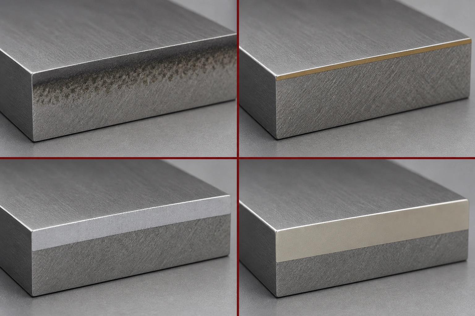
Hard chrome is another wear-oriented surface treatment. Uddeholm lists hard chrome among treatments used to improve mold-surface performance and advises applying surface treatment after the mold has been approved because later machining becomes difficult. [1] The specification still needs the substrate, surface preparation, target thickness, dimensional buildup, masked regions, adhesion check, finish, and repair route; "chrome plated" alone does not define an acceptance condition.
Electroless nickel is useful when uniform coverage over complex shapes or recessed surfaces and a combination of corrosion and wear resistance are priorities. The Nickel Institute distinguishes this uniform chemical deposition from electrolytic plating. [7] Because coating buildup changes the finished geometry, specify the deposit and post-treatment condition, thickness and measurement locations, surface preparation, adhesion criteria, masked areas, and stripping or repair plan. Neither electroless nickel nor hard chrome substitutes for a stable, adequately supported substrate.
Diagnose Failures Without Turning Symptoms Into Proof
Several observations can direct an investigation, but none establishes root cause alone:
| Observation | Plausible contributors to check | Evidence needed |
|---|---|---|
| Insert bows after hardening | Machining stress, asymmetry, support, thermal gradient, transformation | Pre/post map, machining history, furnace record, grade condition |
| Hardness varies by location | Section response, decarburization, test preparation, cycle, material mix-up | Hardness traverse, heat traceability, surface condition, furnace chart |
| Chipping begins near a corner | Low toughness margin, stress concentration, contact, grinding damage | Fracture origin, radius/contact review, hardness, grinding record |
| Flash appears after weld repair | Geometry, local hardness, heat-affected zone, seating, cavity pressure | Dimensions, hardness map, repair record, mold-fit review |
| Gate or runner erodes early | Abrasive filler, local velocity or impingement, unsuitable steel or surface system | Exact resin and filler, gate geometry, baseline and current profile, hardness/coating record, shot-count photos |
| A critical dimension drifts during service | Thermal equilibrium, wear, seating, retained-austenite transformation, tempering or measurement condition | Time- and temperature-stamped steel and part dimensions, furnace/temper record, wear map, measurement setup |
| Rust or pitting appears locally | Condensation, coolant leak, storage practice, corrosive resin by-products or additive package | Location and morphology, coolant and leak check, resin identity, shutdown and maintenance record |
Tool-steel welding creates a heat-affected zone and residual stresses. Uddeholm recommends controlled preheating and a grade- and condition-specific post-weld heat-treatment decision; hardened tools commonly require post-weld tempering, while pre-hardened tools may be stress-relieved depending on the repair and requirements. [6] Flash after a repair does not, by itself, prove that the heat-affected zone softened.
Make the Heat-Treatment Record Part of Mold Acceptance
The handoff package should connect the material to the result: steel producer and grade, heat number, incoming certificate, insert ID, rough-machining and stress-relief sequence, furnace cycle chart, quench method, every temper or subzero cycle, hardness method and locations, pre/post dimensional map, nonconformance disposition, and final coating or surface-treatment record.
Our public rapid tooling service describes our tooling scope, while our mold steel selection guide provides a useful discussion starter for grade choice. Our inspection workflow lists incoming-material, DFM, in-process, and T1 dimensional checkpoints. For a heat-treated mold, use those checkpoints to request the insert-specific records above and agree on which post-treatment dimensions must be verified before assembly and again on molded parts. The exact steel, heat-treatment supplier, hardness target, and acceptance map remain project-specific.
Frequently Asked Questions
How much stock should be left for heat-treat distortion?
There is no universal allowance. Base it on the steel grade, insert dimensions and asymmetry, machining history, heat-treatment route, heat treater's documented experience, critical-feature tolerance, and planned grinding method. Record the allowance by surface rather than as one general note.
Does stress relief eliminate distortion during hardening?
No. It can reduce the contribution from rough-machining stresses when used at the correct stage, but thermal gradients and phase transformation still produce dimensional change. Geometry, support, quench, and finishing stock remain important.
Are two tempering cycles always enough?
At least two are common tool-steel guidance, but the exact grade datasheet governs. Large molds or unusually demanding dimensional-stability requirements may call for a third temper, while temperature and time determine whether the target hardness and microstructure are achieved. [2]
Is PVD better than nitriding for mold inserts?
Not categorically. Nitriding creates a hardened case; PVD adds a thin coating that needs adequate substrate support. Choose from the wear mode, grade, treatment temperature, geometry, tolerance, finish, corrosion environment, and repair plan.
Conclusion
Reliable mold steel heat treatment begins before the furnace. Select hardness from the exact resin system, mold life, geometry, and failure risk; rough-machine and stress-relieve while correction stock remains; harden and temper to the grade-specific procedure; and compare the same dimensional map before and after treatment. Nitriding and PVD can extend the surface performance of a suitable, stable substrate, but neither replaces correct steel, heat treatment, geometry, or measurement.
Sources
[1] Uddeholm: Tool Steels for Plastic Moulding
[2] Uddeholm: Heat Treatment of Tool Steel
[3] ASM Handbook: Control of Distortion in Tool Steels
[4] Oerlikon Balzers: PVD-Based Processes
[5] Oerlikon Balzers: Coatable Materials