-1.png)

A cylindrical part leaves the mold with one wall thicker than its opposite wall. It is tempting to reduce injection speed, change hold pressure, or call the core off-center. Each may be relevant, but the finished part alone does not show when the offset entered the system.
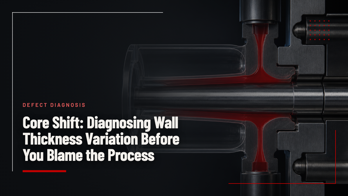
Autodesk uses core shift as a broad term for three sources of dimensional error: machining or setup misalignment, mold and platen deflection, and elastic core deflection caused by an unbalanced pressure field. Its Moldflow core-shift calculation focuses on the third mechanism. [1] That distinction matters. A static eccentricity needs a different correction from a core that begins centered and bends during filling or packing.
Define the Failure Before Adjusting It
In dynamic core deflection injection molding, melt pressure is not equal on every side of the core. The net lateral load bends or translates the core, changing the flow channel. The widened side becomes easier to fill; the narrowed side becomes more restrictive. That fluid-structure interaction can amplify the initial imbalance until the frozen polymer and the core's support restrain further movement.
Long, slender cores and thin-walled containers are particularly sensitive, but susceptibility is not proof of root cause. [1] A practical fault tree should keep at least four branches open:
| Failure layer | Examples | Discriminating evidence |
|---|---|---|
| Static tool geometry | Core machined off-center, insert seating error, worn locator, parting-line mismatch | Cold-tool dimensional and alignment inspection; repeatable offset before molding |
| Mold or machine deflection | Plate, support, platen, or clamp response under pressure | Pressure-dependent pattern; support/contact inspection; mold and machine data |
| Dynamic core deflection | Asymmetric gate arrival or pressure around a flexible core | Staged fill pattern; offset changes along core length or with pressure history; structural-flow analysis |
| Part or measurement behavior | Warpage after ejection, conditioning change, fixture or datum error | Time-resolved measurements; section verification; alternate setup or non-contact scan |
The word "core shift" is acceptable for the observed condition, but the corrective-action record should state which mechanism has been demonstrated.
Build a Wall-Thickness Map, Not One Cross-Section
Measure opposing walls around the full perimeter and at several distances from the supported end. For a tubular feature, four or more angular positions at the base, middle, and free end create a far more useful map than one caliper check. Preserve cavity, shot number, material condition, process settings, and the datum used to locate each section.
A pattern that starts near nominal at the core base and grows toward a free end is consistent with bending. It is not proof: draft, taper, post-mold warpage, measurement alignment, and a mis-machined core can create a similar trend. A nearly constant eccentricity along the length is more consistent with static offset or translation, but that conclusion also needs tool inspection.
Two misdiagnoses deserve an explicit check. First, a weak or cracking region on the thin side may be blamed on resin toughness even though the local load-bearing section is smaller because the inner feature is displaced. Second, different gloss, sink, or cooling marks on opposing walls may be blamed on one-sided packing or temperature even though the actual wall-thickness map is asymmetric. In both cases, measure geometry before treating the visible or mechanical symptom as a material verdict.
Use a method capable of reaching the feature: a prepared section on an agreed plane, CT where resolution and material permit, or accessible inner and outer surfaces measured in one coordinate system. Qualify any indirect wall-thickness method for the specific material and geometry.
State whether the result is local thickness, fitted concentricity, centerline offset, roundness, or profile. These metrics are related but not interchangeable. A compliant average wall can hide a critically thin local region, while a round inner bore can still be eccentric to the outer surface.
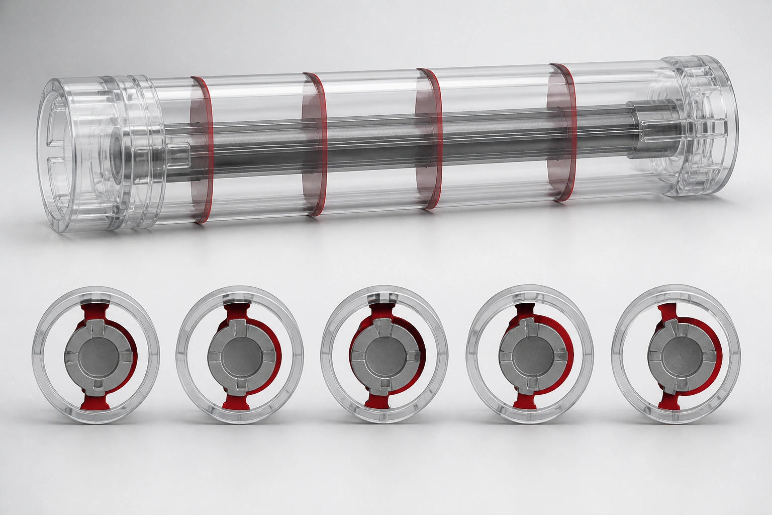
Use Short Shots to Reveal the Loading Sequence
Staged short shots can show whether melt consistently races around one side of the core. Keep material condition, mold temperature, melt preparation, fill-velocity profile, and machine setup fixed while delivered volume is stepped from early entry to near-full fill. Label every cavity and retain several repeat shots at each stage.
Peer-reviewed experiments on a long, thin hollow molding observed asymmetric melt advance and core deflection, then compared measured motion with numerical simulation. The measured and predicted trends were similar, although the simulation predicted larger displacement in that study. [2] Another instrumented study found that nonuniform flow can produce a pressure difference across an insert, and that the magnitude and duration of the load both matter. Gate asymmetry, part geometry, venting, material, and processing can all contribute. [3]
Read the staged parts together with the wall map:
-
A persistent leading side that corresponds to the eventual thick wall supports a fill-driven pressure-imbalance hypothesis.
-
A balanced early front followed by a later offset shifts attention toward end-of-fill, venting, packing, or support response.
-
A wall offset without a repeatable fill-side pattern keeps tool alignment and post-mold warpage high on the list.
-
A result that changes only in one cavity points toward a local gate, vent, insert, or support condition; a common change across all cavities may originate in material or machine conditions.
Short shots reveal fill order, not core displacement by themselves. Add cavity-pressure data, displacement instrumentation, or a validated structural-flow model where risk warrants.
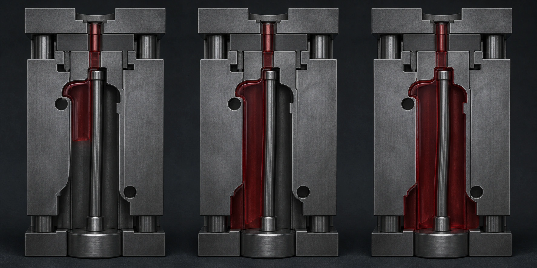
Correct Geometry and Support at the Force Path
The most robust correction usually reduces pressure imbalance, reduces unsupported span, increases section stiffness, or improves the load path into the mold.
Balance the melt around the core
A gate that enters from one side can load the near face before pressure develops around the circumference. An annular, diaphragm, multiple-gate, or otherwise balanced feed concept may improve symmetry, but gate selection must also satisfy vestige, weld-line, degating, material, and tool constraints. Even nominally symmetric gates can become unbalanced through gate dimensions, hot-runner behavior, venting, temperature, or flow restrictions.
Improve core support design
Shorten the unsupported length, increase core diameter where permitted, strengthen its seating, or support the far end. A support can leave a witness mark, create a weld line, complicate ejection, or interfere with the bore, so it belongs in part and mold DFM.
Specify stiffness correctly
"Use harder core steel" confuses wear or strength with elastic stiffness. Elastic bending depends on Young's modulus, geometry, unsupported length, boundary conditions, and load. If a material change is proposed, compare modulus at the relevant temperature; another tool steel with similar modulus may add little stiffness, while geometry and support can add more.
Do not enlarge a core or add support without checking finished wall thickness, cooling, venting, ejection, and assembly. Every tool correction should have an updated section drawing and a measurable hypothesis.
Process Changes Are Diagnostic Levers, Not Universal Cures
Injection speed, melt temperature, mold temperature, transfer point, packing pressure, and packing time can change the pressure field and the time for which it acts. The direction is not always intuitive:
-
Reducing fill speed may lower an inertial or localized pressure imbalance, but it can also increase frozen-layer development and pressure demand.
-
Lowering melt temperature may reduce thermal exposure, but higher viscosity can increase required pressure.
-
Raising mold temperature may delay freezing and improve flow symmetry while extending the interval during which the core can move.
-
Reducing pack pressure may reduce later loading, but can create sink, shrinkage, or dimensional failures elsewhere.
The plan statement that "hold pressure does nothing to core shift" is not generally correct. Autodesk's current core-shift settings allow deformation to continue during packing because cavity pressure continues to act; the model also accounts for restraint as the part freezes. [4]
Change one controlled factor at a time and collect the same wall map, part weight, fill time, peak pressure, cushion, and short-shot evidence. A process change is robust only if it produces conforming walls and all other requirements across the approved window, not at one carefully selected setting.
Use Coupled Simulation for Decisions, Then Validate at T1
A fill-only result can identify an asymmetric pressure field but cannot show how that field changes the flow channel as the core moves. Core-shift prediction is a fluid-structure interaction problem: pressure loads the core, core displacement changes local wall thickness, and the changed channel alters pressure and flow. Autodesk's workflow therefore connects filling and packing with structural response and distinguishes elastic properties, constraints, contacts, and core geometry. [1][4]
Include the released feed system, core and support geometry, elastic properties, contacts, resin model, and fill-pack process. Compare gate, support, core-section, and process alternatives rather than treating one contour as an acceptance certificate.
Model limits need to stay visible. Autodesk warns that large predicted shifts can create mesh instability and reduce accuracy. [4] Published experiments have also found numerical displacement larger than measured displacement in a particular hollow-part study. [2] Use simulation to rank mechanisms and designs, then correlate pressure, wall thickness, and, where possible, core motion at T1.
Verify the Fix With a Repeatable Evidence Package
Before changing steel, record the cold-tool alignment and support; cavity-numbered wall maps; conditioning and measurement method; staged short shots; actual fill-pack, pressure, temperature, and cushion data; simulation assumptions; and the mechanism the proposed correction should change.
After correction, repeat the same measurements under comparable conditions. Confirm minimum local wall, concentricity or profile as specified, roundness, strength or pressure performance, cosmetics, ejection, and dimensional stability over the required conditioning period. One sectioned part can confirm geometry at one instant; it cannot establish process capability.
Our core-and-cavity guide and mold-flow analysis overview provide public design context, while our inspection workflow lists DFM, in-process, scanning, dimensional, and T1 checkpoints. For a core-shift-sensitive part, use the DFM stage to identify the unsupported core, pressure-symmetry risk, required internal measurement method, section planes, sample size, and acceptance metric. Sectioning, CT, displacement sensing, or core-shift simulation should be requested explicitly rather than inferred from a general inspection statement.
Frequently Asked Questions
Is one thick wall opposite one thin wall proof of core deflection?
No. It is consistent with a displaced inner feature, but static machining offset, insert seating, mold deflection, warpage, and measurement setup can produce similar evidence. Compare the cold tool, multiple axial sections, staged fill pattern, and pressure dependence.
Will reducing injection speed stop core shift?
Sometimes it reduces a particular asymmetric load; in other cases the cooler, more viscous flow increases pressure demand or changes which side leads. Treat speed as a controlled experiment and verify the full operating window.
Does hold pressure affect core shift?
It can. Pressure continues during packing, while the growing frozen layer increasingly restrains motion. The net result depends on the part, gate seal, core support, pressure history, and freezing behavior. [4]
Is a harder core less likely to bend?
Not necessarily. Elastic bending is controlled by modulus, geometry, length, support, and load. Hardness is important for wear and strength but is not a substitute for elastic-stiffness data or better core support design.
Conclusion
Core shift injection molding should be diagnosed as a timing and force-path problem. First distinguish static tool offset, mold deflection, dynamic core bending, and post-mold behavior. Then combine a multi-section wall map with cold-tool inspection, staged short shots, pressure history, and coupled simulation. Process settings may help define the mechanism, but balanced filling, adequate section stiffness, and effective core support usually provide the more durable correction. Repeat the same evidence package after the change before declaring the mold fixed.
Sources