
Skip to content

GAS-ASSISTED INJECTION MOLDING

Stronger Parts.
Less Material.

Produce large, structurally efficient plastic parts with hollow sections, lower weight and improved surface quality—all with expert tooling and molding support from prototype validation to production.

  • Reduced Sink Marks
  • Lower Part Weight
  • Improved Structural Rigidity
  • Tooling & DFM Support

HOW THE PROCESS WORKS

Controlled pressure.
Hollow structure.
01

Resin enters
the mold

02

Gas displaces
the molten core

03

Pressure forms
the hollow section

Result

More uniform packing pressure through thick sections

GAS-ASSISTED MOLDING EXPLAINED

What Is Gas-Assisted
Injection Molding?

Gas-assisted injection molding introduces pressurized nitrogen into the molten plastic after an initial resin shot. The gas follows designed flow channels, pushing material toward the mold walls and creating a controlled hollow core inside thicker sections.

The process can reduce material use and clamp-force demand while helping minimize sink marks, warpage and internal stress. It is especially useful for long handles, structural frames, panels and other parts that combine thick features with demanding cosmetic surfaces.

01

Hollow Thick Sections

Designed gas channels remove unnecessary material from heavy areas.

02

Cleaner Surfaces

Internal pressure supports the outer wall to reduce visible sink marks.

03

Efficient Structures

Lower part weight can be achieved without sacrificing functional stiffness.

PROCESS ADVANTAGES

Better Part Performance.
Smarter Material Use.

Gas assistance improves how pressure is distributed through thick and complex sections, helping manufacturers achieve lighter parts, cleaner surfaces and more efficient production without compromising function.

01 CORE ADVANTAGE

Lower Weight with Structural Integrity

Controlled hollow channels replace unnecessary solid material in thick regions while preserving the external geometry and functional stiffness of the component.

02

Reduced Sink Marks

Gas pressure packs the resin against the cavity wall as the part cools, improving appearance across thick features and ribs.

03

Improved Dimensional Stability

More uniform internal pressure can reduce uneven shrinkage, distortion and residual stress in suitable part geometries.

04

Lower Molding Pressure

The gas assists resin flow and packing, which can reduce peak injection pressure and clamp-force requirements.

05

Greater Design Freedom

Thick handles, long flow paths and integrated structural features become practical without molding every section as a solid mass.

HOW GAS-ASSISTED MOLDING WORKS

From Resin Fill to
Controlled Hollow Core.

Resin volume, gas timing and pressure are coordinated with the part and runner design to create a repeatable hollow section while maintaining the required exterior geometry.

01 PARTIAL FILL

Resin Injection

A controlled shot of molten polymer enters the mold cavity, filling the designed flow path without completely packing the thick section.

02 GAS ENTRY

Nitrogen Injection

Pressurized nitrogen is introduced through a gas pin or nozzle and advances along the intended channel inside the molten material.

03 PACK & COOL

Pressure Hold

Gas pressure pushes resin against the cavity surface during cooling, helping compensate for shrinkage and support the outer wall.

04 VENT & EJECT

Gas Release & Ejection

After sufficient cooling, the gas is safely vented or recovered and the finished part is ejected with its hollow section formed.

PROCESS CONTROL

Gas entry location, resin shot size, delay time, pressure profile and cooling time are validated for each tool and part geometry.

MATERIAL OPTIONS

Choose a Resin That Supports
Both Flow and Function.

Material choice affects gas penetration, surface finish, stiffness, impact performance and the final process window. We match the resin to your design, environment and production requirements.

FLOWSURFACESTRENGTHHEATIMPACT
01

BALANCED PERFORMANCE

Commodity Resins

  • Polypropylene (PP)
  • High-Impact Polystyrene (HIPS)
  • ABS

A practical choice for many handles, housings and consumer or automotive components that need balanced cost, appearance and impact performance.

03

REINFORCED GRADES

Filled Materials

  • Glass-Filled PP
  • Glass-Filled PA
  • Mineral-Filled Grades

Suitable when stiffness or dimensional stability must be enhanced; flow behavior and fiber effects are reviewed during DFM.

MATERIAL REVIEWNeed help selecting a resin?

Share your operating conditions, performance targets and finish requirements for an engineering recommendation.

Talk to an Engineer

SUITABLE PART APPLICATIONS

Where Hollow-Core Design
Makes the Difference.

Gas-assisted molding is a focused solution for parts that need long flow paths, thicker structural zones or a cleaner visible surface than conventional molding can efficiently deliver.

APPLICATION GUIDE01—04
01

Handles & Grips

Long carry handles, interior grab handles and ergonomic equipment grips.

02

Structural Components

Reinforced frames, seat structures and load-supporting plastic members.

03

Large Cosmetic Parts

Panels and housings where thick transitions can otherwise create sink marks.

04

Integrated Assemblies

Complex parts combining ribs, bosses, mounts and hollow structural channels.

Gas-assisted injection molded structural plastic components
DESIGNED GAS PATHMaterial is moved where it adds function—not unnecessary mass.
IS GAS-ASSISTED MOLDING A FIT?

We review wall transitions, expected load, gate and gas-entry locations, and cosmetic requirements before recommending a tool strategy.

Send Us Your Part

ENGINEERING GUIDANCE

Design the Gas Path.
Then Build the Tool.

DFM FIRST

Gas-assisted molding is engineered around a deliberate gas channel. Early review aligns material flow, structural loading, surface requirements and the molding process before tooling begins.

01FLOW STRATEGY

Plan the Gas Channel

Route gas through thicker, non-cosmetic sections where material can be displaced without affecting critical part features.

02PART GEOMETRY

Manage Wall Transitions

Smooth thickness changes help resin and gas advance predictably and reduce restrictions along the designed flow path.

03TOOL LAYOUT

Choose the Gas Entry

Gate and gas-pin locations are coordinated so gas enters only after the initial resin shot reaches the intended area.

04PROCESS CONTROL

Define Gas Exit & Venting

Venting or overflow design controls final gas position and supports a stable, repeatable molding process window.

APPLICATION EXAMPLE / 01

A White Structural Handle.
Built Around a Hollow Core.

This representative component uses gas assistance to create a substantial curved grip section with integrated mounting points, without turning that thick section into a solid mass.
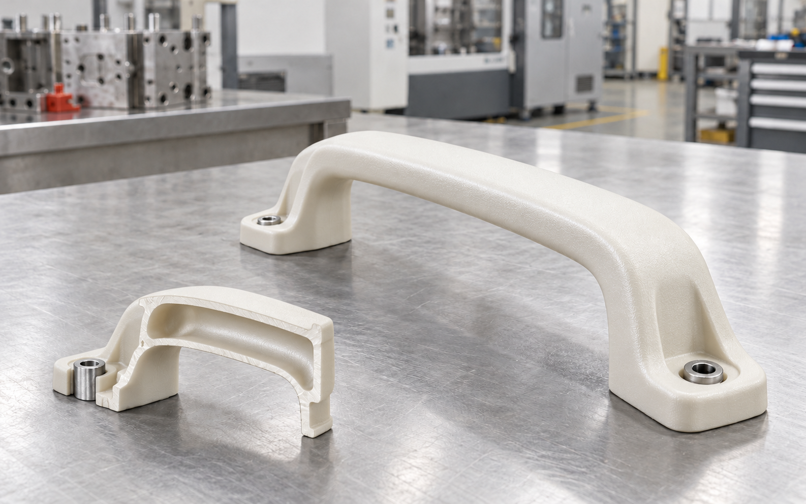
White gas-assisted molded structural handle with hollow core cutaway
WHITE GAS-ASSISTED HANDLE

Representative hollow-core construction

THE ENGINEERING BRIEFCreate a rigid, clean-finish white handle with a substantial curved section—while managing material use and visible-surface quality.

01

Hollow Core

Gas displaces resin through the thicker grip section.

02

Surface Support

Internal pressure supports the outer cavity wall while cooling.

03

Integrated Mounting

Reinforced mounting areas remain part of the same component.

READY TO REVIEW YOUR PART?

Turn Thick Sections Into
Smarter Molded Parts.

Send us your 3D file or drawing. Our engineering team will assess part geometry, wall transitions and gas-channel potential before proposing the right tooling approach.

Request a Manufacturing Review DFM feedback · Tooling support · Production-ready molding

FAQ

Gas-Assisted Molding
Questions, Answered.

Practical answers about part suitability, materials, tooling and production support for gas-assisted injection molding projects.

Still evaluating your part?

Send your CAD model, wall sections, material preference and expected quantity. Our engineers will review whether gas assistance is a practical option.

Get a Quote
01What is gas-assisted injection molding?

It is an injection molding process where pressurized inert gas is introduced into selected thick sections of a part. The gas forms controlled hollow channels, helping reduce material use, sink marks and part weight while supporting rigidity.

02What types of parts are suitable for gas assistance?

It is often considered for parts with substantial curved sections, long flow paths, thick structural zones or visible surfaces where conventional molding may create sink marks. Handles, frames, housings and integrated structural components are common examples.

03Can gas assistance improve visible surface quality?

In suitable geometries, internal gas pressure can help hold resin against the cavity surface during cooling. This may reduce sink marks around thicker sections, ribs and transitions, subject to material, tool design and process validation.

04Which materials can be used?

Many commonly molded engineering and commodity resins can be evaluated, including PP, ABS, HIPS, PC/ABS, PA and selected filled grades. Final suitability depends on flow behavior, wall thickness, required properties and the intended gas path.

05Does gas-assisted molding require a special mold?

Yes. The mold needs planned gas-entry locations, venting, suitable wall transitions and tooling features that support the intended gas channel. We review these requirements during DFM and tool design.

06Can you help determine whether my part is a good fit?

Yes. Share a 3D model or drawing with expected material, quantity, appearance requirements and critical features. We can review the geometry and recommend whether gas-assisted molding or another process is the more practical route.

Get Quote
Get instant pricing, project lead times, and DFM feedback.
doc|docx|ppt|pptx|pdf|jpg|png|STEP|STP|STL|ZIP|RAR
IGES|IGS|SLDPRT|3DM|SAT or X_T files