

Flash is a symptom, not the root problem. Lower the pressure to make it go away and a short shot usually shows up somewhere else on the part instead, which is exactly the "flash and shorts chase" that wastes hours on the production floor. Permanently fixing flash means identifying which of a handful of root causes is actually responsible, rather than nudging process parameters until the visible symptom disappears.
This guide breaks flash down by root cause, shows how to read the flash pattern itself for diagnostic clues, and separates permanent fixes from the process band-aids that only delay the next occurrence.
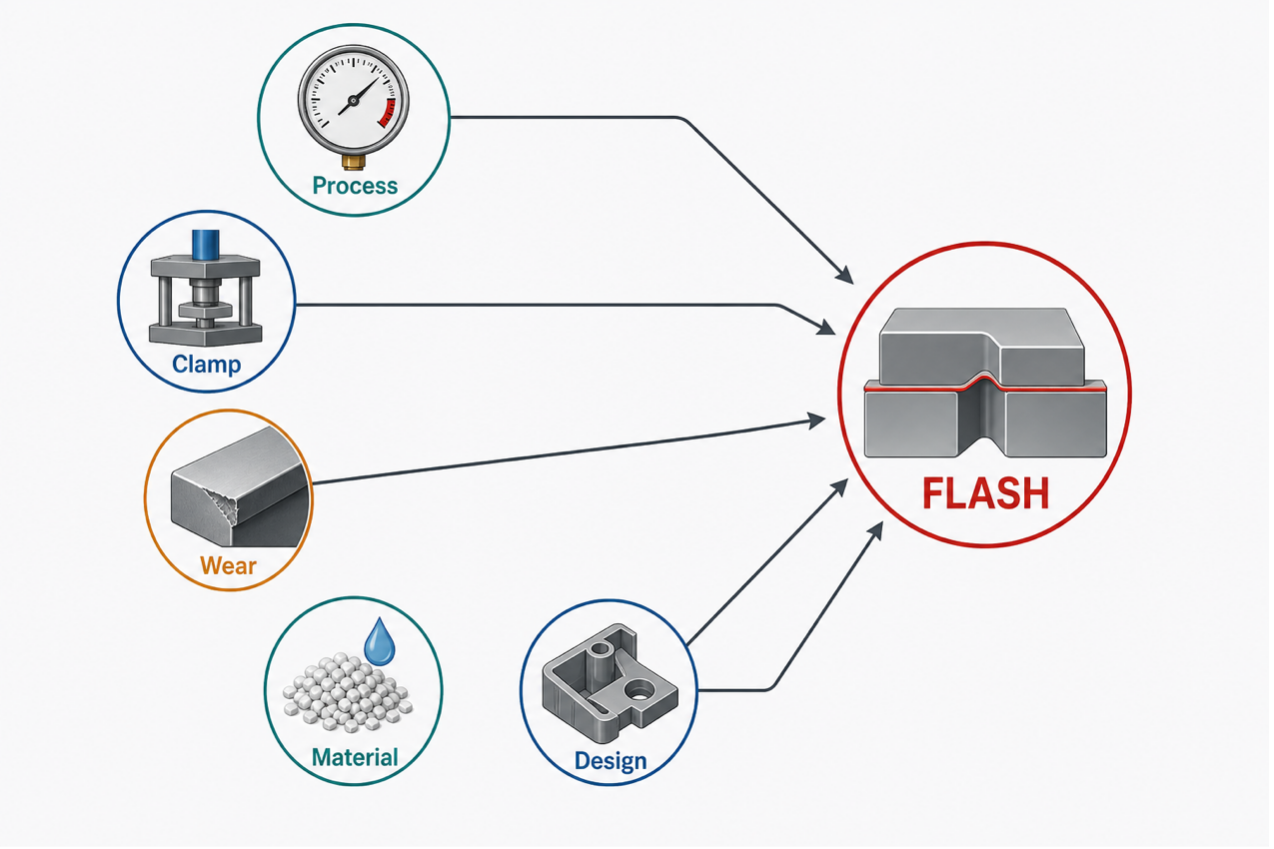
Five Root Cause Categories
Flash forms when molten plastic finds a path out of the cavity that shouldn't exist, and that path traces back to one of five categories.
Process: Overpacking and Excess Shot Size
Excessive packing pressure, excessive shot size, or overly aggressive process settings can generate cavity pressure beyond what the mold system can contain. A controlled study of micro-injection molding found that injection speed and packing pressure were the most influential parameters for increasing flash formation across two different materials, with higher melt and mold temperature settings showing a comparatively smaller effect on flash amount [1]. That ranking matters for troubleshooting: when flash shows up, packing pressure and injection speed are often among the first process parameters to review, but they should be evaluated together with tooling condition and clamp force.
Clamp Force: Cavity Pressure Exceeding Tonnage
If the clamp force available on the press is lower than the force the melt exerts against the mold during fill and pack, the mold halves separate slightly and plastic escapes at the parting line. This is primarily a clamp force versus cavity pressure issue, and it often appears consistently when the process conditions remain unchanged.
Mold Wear: Worn Parting Lines and Damaged Shut-Offs
Thousands of open-close cycles under high pressure wear the parting line surfaces, and that wear creates a gap that wasn't there when the mold was new. Worn shut-offs on sliding cores behave the same way. Process adjustments can mask this for a while, but the gap only grows with more cycles.
Material: Low-Viscosity Resins and Batch Inconsistency
Lower-viscosity material flows into smaller gaps more readily than a higher-viscosity grade at the same pressure. A separate process study found that one material (PP) showed consistently more flash than another (ABS) under matched process settings on the same mold [1], which means a material substitution, even one with similar nominal properties, can shift a previously flash-free process into flash territory.
Design: Sharp Transitions and Inadequate Draft
Poor shut-off design, insufficient sealing surfaces, or inadequate draft on sliding features can allow gaps to open under molding pressure, and inadequate draft on sliding elements increases the likelihood of a gap opening under load. These are tooling design issues, not process issues, and no amount of parameter tuning fixes a design-level cause.
How to Read the Flash Pattern
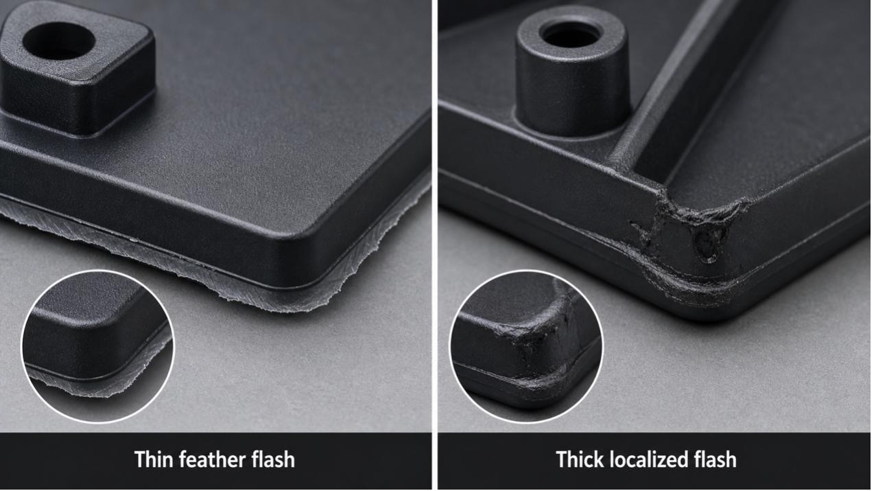
The physical appearance of the flash itself narrows down which root cause is most likely before a single process parameter gets changed.
Thin and Feather-Like Flash
A thin, feather-like flash usually indicates that molten plastic is entering a very small gap under pressure. Injection speed, packing pressure, material viscosity, mold temperature, and venting conditions can all influence how easily this happens.
Thick and Localized Flash
Thick flash concentrated in one area typically points toward a localized tooling issue, such as worn shut-offs, damaged inserts, poor alignment, or uneven mold support.
Patterns Across Multiple Molds on the Same Press
If flash appears across several different molds run on the same press, the press itself is the more likely suspect. Platen parallelism issues affect every mold mounted on that machine, not just one.
Sudden Onset on a Previously Good Mold
When a mold that ran clean for months suddenly starts flashing, the diagnostic priority is finding what changed (a new material lot, an operator change, a maintenance event) before touching any process parameter. Adjusting pressure or speed without first identifying the change risks solving today's symptom while leaving the actual cause to resurface later.
Permanent Fixes by Root Cause
|
Root cause |
Process band-aid |
Permanent fix |
|
Worn tooling |
Lower pressure |
Refurbish parting surfaces |
|
Insufficient clamp |
Reduce shot size |
Larger press or fewer cavities |
|
Process settings |
Trial and error |
Scientific molding to map the window |
|
Low-viscosity material |
Slow down injection |
Design flash grooves into the mold |
|
Contamination |
Clean once |
Implement a regular cleaning schedule |
A Taguchi-based design of experiments study on polypropylene parts identified holding pressure and mold temperature as the significant factors contributing to both warpage and gate flash simultaneously, and validated that an optimized combined setting produced a significant reduction in rejection rate compared to the original process settings [2]. The key finding worth generalizing: flash and other defects often share root causes in the same parameter set, so fixing flash in isolation without checking warpage or sink marks can undo a different defect's tuning.
The Flash-Short Shot Chase
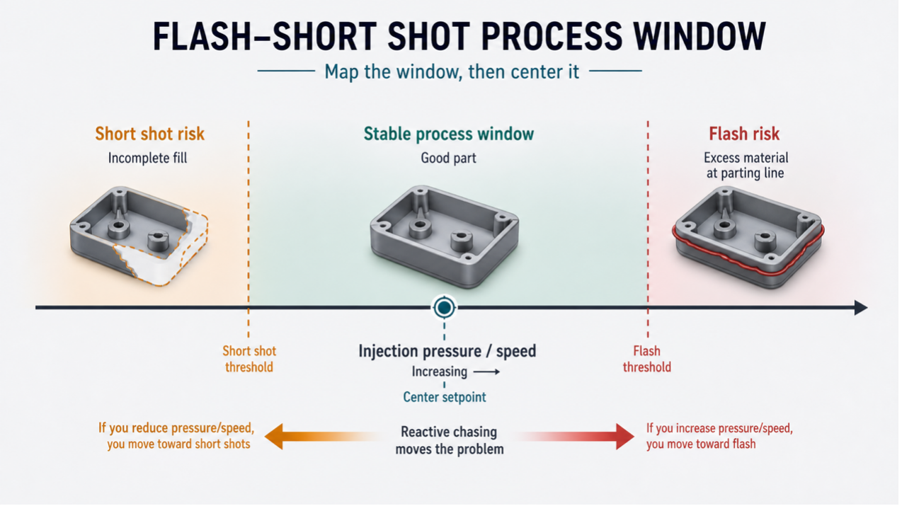
Flash and short shots sit at opposite edges of the same process window, which is exactly why operators chasing one defect with a single-parameter adjustment frequently create the other.
Why These Two Defects Travel Together
Reducing pressure or speed to eliminate flash pushes the process toward the short-shot boundary. Increasing either to fix a short shot pushes back toward flash. Without a wider view of the full process window, an operator can spend a shift oscillating between the two boundaries without ever finding the stable middle.
Scientific Molding: Mapping the Window, Then Centering
Scientific molding maps the full process window from short shot to flash boundary first, then deliberately centers the production setpoint away from both edges, rather than setting parameters reactively each time a defect appears. The Trotta et al. study on flash probability found that the probability of flash formation increased with melt temperature, holding pressure, mold temperature, and injection speed across the parameters they tested [3], underscoring that nearly every lever available to fix a short shot also moves the process toward the flash boundary; centering the window, not chasing a single defect, is what keeps both in check.
Prevention Checklist
- DFM review of parting line placement before tooling is cut
- Proper draft specified on all shut-offs and sliding cores
- Regular mold preventive maintenance with parting surface inspection
- Clamp force verified as adequate at actual production shot conditions, not just at quoting
- Operators trained to read flash patterns before adjusting any parameter
Getting to the Root Cause Before It Costs a Production Run
Many recurring flash problems are treated as process issues even when the underlying cause is related to tooling condition or mechanical factors. HordRT approaches recurring flash defects through root cause analysis as part of our injection molding services, starting with mold inspection and clamp force verification before any process parameter is touched. One limitation worth flagging: diagnosing a wear-related root cause on a customer-supplied legacy mold sometimes requires disassembly time that wasn't budgeted in the original tooling quote, so flagging a flash history upfront during quoting avoids a mid-production surprise.
Conclusion
Flash problems are resolved more reliably when troubleshooting starts with the pattern and the mold, not the process panel. Diagnose what the flash looks like and where it shows up, verify the mold's actual condition, confirm clamp force is adequate for the real shot, and only then tune the process. That order, repeated consistently, saves more time and material than any single parameter tweak ever will.
Sources
- "Effect of Process Parameters on Flow Length and Flash Formation in Injection Moulding of High Aspect Ratio Polymeric Micro Features." Micromachines / PMC, National Center for Biotechnology Information. https://www.ncbi.nlm.nih.gov/pmc/articles/PMC6187336/
- Yang, Y.K., Shie, J.R., Liao, H.T., Wen, J.L., Yang, R.T. "A Study of Taguchi and Design of Experiments Method in Injection Molding Process for Polypropylene Components." Journal of Reinforced Plastics and Composites, Vol. 27, p. 819, 2008. https://www.researchgate.net/publication/258156988
- Trotta, G., Cacace, S., Semeraro, Q. "Optimizing process parameters in micro injection moulding considering the part weight and probability of flash formation." Journal of Manufacturing Processes, Vol. 79, pp. 250-258, 2022. https://www.sciencedirect.com/science/article/abs/pii/S1526612522002857


-2.png)