CNC machining stands as a cutting-edge manufacturing technique, enabling the accurate and effective fabrication of intricate parts and components. The CNC machines follow coded instructions to create highly accurate and complex designs, making them an essential tool in industries ranging from aerospace to medical devices. However, achieving such precision requires adherence to specific standards known as CNC tolerance standards. These standards play a crucial role in ensuring that the final products meet the desired specifications and functional requirements.
Understanding CNC Tolerance
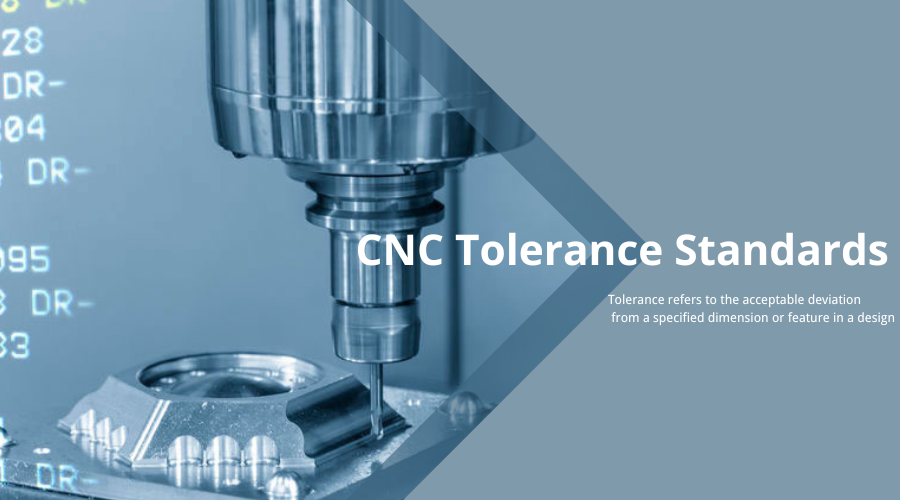
Tolerance refers to the acceptable deviation from a specified dimension or feature in a design. In CNC machining, parts are rarely produced with absolute perfection due to various factors such as material properties, machine capabilities, and environmental conditions. CNC tolerance standards define the allowable range of variation for dimensions, geometries, and surface finishes of manufactured parts. Tolerances are usually indicated on technical drawings using symbols, such as “+/-0.005mm,” which specifies the range within which the actual dimension can vary.
Importance of CNC Tolerance Standards
1. Geometric Dimensioning and Tolerancing (GD&T)
This system uses standardized symbols to communicate complex tolerances for features like flatness, parallelism, angularity, and more. GD&T provides a comprehensive way to define tolerances that cannot be easily conveyed using traditional linear dimensions.
2. ISO Tolerance Standards
The International Organization for Standardization (ISO) has developed a range of tolerance standards that are globally recognized and widely used. These standards ensure consistency and interoperability across different countries and industries. Some common ISO tolerance standards include:
ISO 2786: General tolerances for linear and angular dimensions without individual tolerance indications. It defines basic tolerances for various size ranges.
ISO 286: ISO system of limits and fits. This standard establishes the relationships between hole and shaft tolerances for proper assembly.
ISO 1101: Geometrical tolerancing standards that define symbols and principles for specifying tolerances on geometric features like straightness, circularity, and profile.
ISO 8015: Fundamental tolerance principle, which introduces the concepts of Maximum Material Condition(MMC) and Least Material Condition (LMC) to guide tolerance specification.
3. DIN Standards
A DIN standard is a standard drawn up at the German Institute for Standardisation (DIN) in Berlin that sets unified standards for products and processes, such as quality, minimum performance, characteristics, dimensions, etc. These standards cover a wide range of industries, including mechanical engineering.
4. ANSI Standards
This American National Standard covers preferred fits between mating parts, defining combinations of hole and shaft tolerances. It helps designers select appropriate fits for specific applications.
Challenges and Considerations
- Material Variability:Different materials respond differently to machining processes, which can impact dimensional accuracy. Manufacturers need to consider material properties when setting tolerances.
- Machine Capabilities: CNC machines have their limitations in terms of accuracy and repeatability. Understanding a machine’s capabilities is vital for determining appropriate tolerances.
- Environmental Factors:Temperature, humidity, and other environmental conditions can influence machining accuracy. Manufacturers might need to account for these factors when setting tolerances.
- Communication: Effective communication between designers, engineers, and manufacturers is essential. Clear documentation of tolerances on technical drawings ensures everyone is on the same page.
Wrapping up
In conclusion, CNC tolerance standards are the backbone of precision manufacturing. They enable industries to produce high-quality, reliable, and functional products while striking a balance between cost and performance. Adherence to these standards ensures that the end products meet design specifications, contributing to the advancement of technology and innovation across various sectors. As manufacturing techniques continue to evolve, staying updated with the latest CNC tolerance standards is crucial for maintaining competitiveness and delivering top-notch products to the market.