Johnny Xiong
Rapid Tooling Expert
Contents
Injection molding is one of the most efficient manufacturing processes for producing high-volume plastic parts. However, achieving high-quality, repeatable results is often more complex than it appears. At HordRT, we know that unseen forces are often the biggest threat to product quality. The most critical of these is injection molding stress.
If not managed correctly, stress can ruin part geometry, compromise structural integrity, and lead to costly production failures. In this guide, we will explore where injection molding residual stress comes from, how it manifests as common injection molding defects, and how we use Design for Manufacturing (DFM) principles to solve these issues before they happen.
Causes of Stress in Injection Molding
Stress in plastic parts isn’t random; it is a matter of physics. To solve it, we must first understand its origins. In our experience at HordRT, residual stress generally stems from two primary sources: flow-induced factors and thermal factors.
1. Flow-Induced Stress
This occurs during the filling and packing stages. As the molten polymer is pushed into the mold, the polymer chains are stretched and aligned in the direction of the flow.
- High Shear: When injection speeds or pressures are too high, the material experiences high shear forces near the cavity walls. This forces the molecular chains to orient heavily, creating tension.
- Manifestation: This tension often remains "frozen" in the part, leading to weak points like weld lines (where flow fronts meet) or flow hesitation in thin sections.
2. Thermal Stress
This type of stress is generated during the cooling phase. Polymers shrink as they cool, but they rarely cool evenly.
- Uneven Cooling: If the mold temperature is inconsistent, or if the part design has varying wall thicknesses, different areas of the part will shrink at different rates.
- Volume Contraction: As the melt solidifies, the volume decreases. If the core cools slower than the skin, the core creates internal tension as it pulls against the already hardened outer layer.
3. Residual Stress (The Aggregate Result)
Injection molding residual stress is essentially the combination of flow-induced and thermal stresses remaining in the part after ejection. It is frequently caused by preventable mold design issues or improper processing settings.
How Stress Appears in Molded Parts
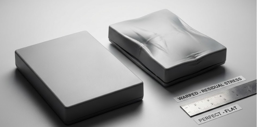
You might not see stress immediately upon ejection, but it will eventually reveal itself. Stress seeks equilibrium, and as the plastic tries to relax, it results in specific injection molding defects.
Here are the most common symptoms we encounter:
- Warping: This is the most prevalent issue. Stress leads to anisotropic shrinkage (where the material shrinks differently along the flow direction versus perpendicular to it). When shrinkage varies across the part, the part twists or bows to relieve the tension.
- Cracking (Stress Cracking): If the internal tension exceeds the material's tensile strength, the part will crack, either immediately upon ejection or later under service loads.
- Whitening: High stress levels can cause "stress whitening," visible as pale marks on the plastic, indicating the polymer chains are being pulled apart.
- Shrinkage Variations: Inconsistent stress leads to unpredictable dimensions, making it impossible to hold tight tolerances.
- Reduced Part Lifespan: Even if the part looks perfect, significant internal tension acts as a pre-load. This reduces the part's ability to withstand external forces or chemical exposure, leading to premature failure.
Practical Solutions To Reduce Stress
At HordRT, we believe that quality is designed in, not inspected in. Reducing injection molding stress requires a holistic approach involving design, mold engineering, processing, and material selection.
1. Design Optimization
The most effective way to eliminate stress is through proper part design.
- Uniform Wall Thickness: This is rule number one. Constant wall thickness ensures uniform flow and cooling. Avoid abrupt changes; if you must change thickness, use a gradual transition to reduce stress concentration.
- Radii and Corners: Sharp corners are stress concentrators.
- Recommendation: We recommend an inside radius of at least 50% of the nominal wall thickness (0.5T). The outside radius should be the inside radius plus the wall thickness (1.5T).
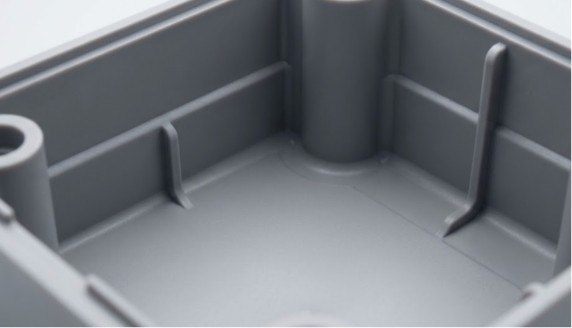
- Ribs and Bosses: Heavy features cause sink marks and voids (stress).
- Ribs: Should be 50% to 75% of the nominal wall thickness.
- Bosses: The radius at the base of a boss should be 25% of the wall thickness (0.25T), with a minimum of 0.015 inches. Always hollow out bosses to the bottom to maintain uniform wall thickness.
2. Mold Improvements
- Gate Placement: We position gates to allow flow from thick to thin sections, ensuring the part packs out properly without over-pressurizing thin areas.
- Balanced Runners: A balanced runner system ensures every cavity fills at the same time and pressure, reducing variations between parts.
- Venting: Trapped air causes burns and forces the injection machine to work harder, increasing shear stress. Proper venting is non-negotiable.
3. Processing Adjustments
Optimizing the process window is crucial for managing residual stress.
- Melt Temperature & Injection Speed: Higher temperatures can reduce viscosity and flow stress, but require longer cooling. We balance this with injection speed to minimize shear.
- Holding Pressure: Sufficient pressure is needed to compensate for shrinkage, but over-packing packs stress into the part.
- Cooling Time: Ejecting a part too hot allows it to warp outside the mold. Adequate cooling time inside the mold constrains the part until it is stable.
4. Material Selection
Choosing the right resin can drastically lower stress risks.
- Low-Stress Resins: High-flow resins generally require less injection pressure, resulting in lower flow-induced stress.
- Amorphous vs. Semi-Crystalline:
- Amorphous materials (like ABS, PC) generally have lower shrinkage and better dimensional stability. They tend to be more isotropic (shrink evenly).
- Semi-crystalline materials (like Nylon, PP) shrink more and are often anisotropic, making them more prone to warping, though they offer superior chemical resistance.
- Fiber Reinforcement: Adding fibers increases strength but can increase anisotropic shrinkage (warping) if fiber orientation isn't managed during the flow analysis.
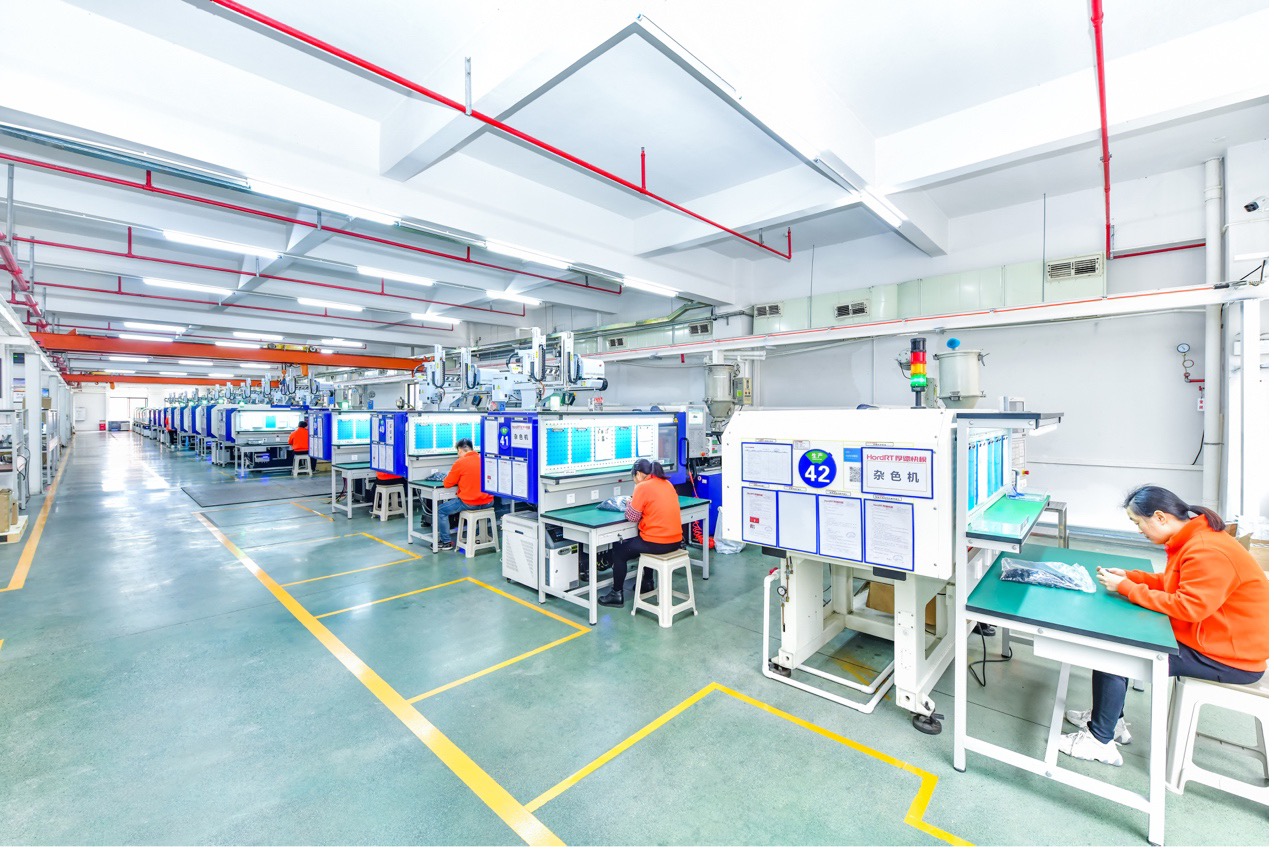
HordRT's Injection Molding Support
With 11 years of experience in global manufacturing, HordRT goes beyond just "making parts." We act as your engineering partner to mitigate risks like injection molding stress before steel is ever cut.
We offer comprehensive support to ensure your project succeeds:
- Design for Manufacturing (DFM) Analysis: We provide detailed design reviews to identify varying wall thicknesses, sharp corners, and potential stress points.
- CAE / Moldflow Analysis: Using advanced Computer-Aided Engineering (CAE), we simulate the injection process. This allows us to test gate locations, predict weld lines, and visualize shrinkage patterns digitally, optimizing the mold design to save costs and time.
- Material Recommendations: Whether you need general-purpose plastics or engineering-grade resins, we help you select materials that balance performance with processability.
- From Prototype to Mass Production: We offer rapid injection molding services using production-grade materials. this allows you to physically validate your design’s geometric stability before committing to high-volume tooling.
Conclusion
Managing injection molding stress is the key to producing durable, high-precision plastic parts. By addressing flow-induced and thermal stresses through optimized design, smart mold engineering, and precise process control, you can eliminate defects like warping and cracking.
At HordRT, we combine expertise with technology to deliver parts that meet the highest standards of quality.
Ready to start your next project? Contact HordRT today for an instant quote. Let our engineering team use our professional DFM analysis and custom engineering capabilities to solve your most complex application requirements.