Johnny Xiong
Rapid Tooling Expert
Contents
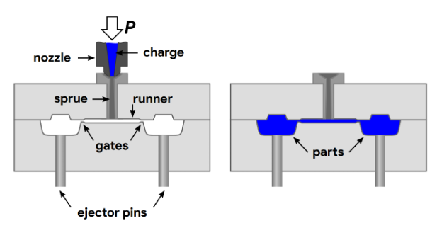
In the intricate world of injection molding, a seemingly small opening—the gate—plays a profoundly critical role in determining the success and quality of a molded part. This aperture is the primary conduit through which molten plastic flows from the runner system into the mold cavity. Far from being a minor detail, the design of the injection molding gate directly influences critical factors such as the cosmetic appearance of parts, the efficiency of production cycle times, and the integrity of part features. An expertly optimized gate design is essential for achieving ideal material flow, significantly reducing flaws, and enhancing overall moldability.
What Is a Gate in Injection Molding?
At its core, a gate in injection molding is the precise point of entry where the molten polymer transitions from the runner system into the intricate geometry of the part. Functioning much like a sophisticated valve, the gate precisely regulates the flow rate, pressure, and subsequent cooling of the molten plastic. These controls are instrumental in determining the ultimate quality and characteristics of the final product. Beyond material delivery, the gate also plays a vital role in mitigating air entrapment as the material enters the cavity, which is a common cause of surface imperfections. After molding, the residual material at this entry point, often called a vestige or gate mark, needs removal, either manually or through automated processes.
Common Types of Injection Molding Gates
The diverse landscape of injection molding applications necessitates a variety of gate types, each with distinct characteristics, advantages, and disadvantages.
- Edge Gate: One of the most prevalent methods, edge gates introduce material at the main parting line. They are simple to machine and modify, making them versatile, and are well-suited for larger parts or components with thicker wall sections. They offer uniform filling and packing with minimal flow resistance, but typically require manual or automated cutting for removal, leaving a visible vestige.
- Submarine/Tunnel Gate: Also known as tunnel or subgates, these are machined below the mold's parting line and are designed for automatic trimming during part ejection. This results in virtually invisible or hidden gate marks, offering excellent aesthetic qualities. However, they are generally suitable for smaller parts due to their smaller cross-sectional area.
- Pin Gate: These small, circular gates are often positioned on the part's surface and typically require a three-plate mold design. Pin gates offer minimal gate marks, making them ideal for high-precision parts where aesthetics are important, especially when the vestige can be located on a non-cosmetic surface. They facilitate automated shearing during ejection.
- Fan Gate: A variation of the edge gate, fan gates are characterized by their wide, fan-like shape, ensuring even distribution of molten plastic over a larger area. They are ideal for larger, flat components or parts with thick walls, promoting consistent filling and minimizing defects like flow lines and jetting.
- Diaphragm Gate: Specifically designed for molded parts with large open diameters or open-ended cylindrical components. They ensure an even flow of material, crucial for mitigating large knit lines and promoting consistent shrinkage. The primary disadvantage is the necessity for a secondary operation to shear off the gate.
- Hot Tip Gate: These gates utilize a heated nozzle to maintain the plastic at its optimal temperature as it flows into the mold. They are highly effective in reducing vestiges, making them well-suited for cosmetic parts, and their central placement helps to center press-clamping forces. However, they can sometimes leave "blush" or flow marks on cosmetic surfaces.
Edge Gate
Located on the parting line, simple to machine, and suitable for thicker parts.
Advantage: Low cost, stable filling
Submarine Gate
Positioned below the parting line for automatic trimming when the mold opens.
Advantage: Good cosmetics, auto-trims
Pin Gate
Used with three-plate molds, leaves a tiny mark, ideal for precision parts.
Advantage: Minimal vestige, flexible location
Fan Gate
A wide opening for even filling across large, flat, or thin-walled areas.
Advantage: Reduces flow lines & warpage
Diaphragm Gate
Designed for hollow cylindrical parts to prevent weld lines and ensure even flow.
Advantage: Uniform filling, high strength
Hot Tip Gate
Leaves no gate vestige, reducing waste. Ideal for high-quality cosmetic parts.
Advantage: No vestige, shorter cycles
Gate Placement: Why It Matters
The strategic positioning of the gate is a foundational element in injection molding, profoundly influencing material flow, pressure distribution, and the overall quality of the final part.
- Impact on Defects: Gate location directly affects the formation of various defects. Improper placement can lead to jetting (excessive velocity creating streaks) , flow lines (visible streaks from inconsistent flow) , and blush (circular patterns around hot tip gates). It also influences weld lines or knit lines (where flow fronts meet) , sink marks and voids (depressions or internal cavities from uneven cooling or insufficient packing) , and warpage (deformation due to uneven cooling).
- Guidelines for Ideal Placement:
- Near Thick Sections: A fundamental guideline is to locate the gate closest to the thickest wall section of the part. This ensures complete packing and facilitates superior pressure holding, preventing sink marks and voids.
- Away from Cosmetic Surfaces: As gates inevitably leave a mark, designers strive to position them in less visible or easily concealed areas.
- Consider Multiple Gates for Large Parts: For large or complex geometries, employing multiple gates significantly improves filling and packing efficiency by reducing flow distances and ensuring even material distribution. This also helps reduce localized defects like weld lines and warpage.
👍Design Principles (Do's)
Place in Thickest Section
Ensures the thick section receives adequate packing pressure, preventing sink marks and voids.
Avoid Critical Cosmetic Surfaces
Keeps the gate vestige in a non-visible area to maintain the part's aesthetic appeal.
Use Multiple Gates for Large Parts
Shortens melt flow distance for more uniform filling and packing, reducing stress and warpage.
👎Defects to Avoid (Don'ts)
Prevent Jetting & Flow Lines
Improper gate location can cause the melt to 'jet' into the cavity, leaving visible streaks.
Reduce Sink Marks & Voids
The gate must feed thick sections continuously; otherwise, uneven cooling causes surface depressions.
Minimize Weld Lines & Warpage
Optimize gate location to control how melt fronts meet and to reduce deformation from uneven cooling.
How to Determine Gate Size in Injection Molding
Gate size is a paramount consideration, directly controlling the flow of molten material into the mold cavity. It influences flow rate, pressure, and cooling dynamics.
- Key Factors Influencing Gate Size:
- Resin Type: Amorphous polymers, fiber-reinforced resins, and heavily filled materials generally require larger gate sizes to minimize temperature rise due to friction and reduce required flow pressure.
- Part Geometry and Thickness: Larger parts necessitate larger gates to support higher-volume flow, while smaller or thinner parts are better suited for smaller gates.
- Required Pressure and Fill Time: Gate size directly influences flow rate and pressure. Undersized gates restrict flow, leading to short shots, increased resistance, and excessive shear heating. Conversely, oversized gates can cause uneven filling and part distortion. There is an optimal filling time that correlates with the minimum injection pressure.
- General Sizing Considerations: As a general rule, the overall gate size should be between 40% and 70% of the nominal wall thickness of the part. Gate thickness typically ranges from 50% to 80% of the nominal wall thickness, and for optimal flow, the gate width should generally be twice the gate thickness.
- Emphasizing Balance: The "optimal" gate size is a dynamic equilibrium between maximizing control over packing, avoiding excessive pressure drop, and maintaining acceptable shear rates. It's about achieving enough flow to fill the mold completely without causing defects like flash or overpacking.
Resin Properties
High-viscosity or fiber-reinforced resins require larger gates to reduce shear heat and flow resistance.
Part Geometry
Larger parts and thicker wall sections need larger gates to allow for sufficient material volume and packing.
Processing Conditions
Gate size directly controls fill rate. It must be optimal for the required fill time and injection pressure.
General Sizing Guideline
As a rule of thumb, gate thickness should be between 50% to 80% of the part's nominal wall thickness.
Design Tips for Optimizing Gate Design
Optimizing gate design is a multifaceted process that benefits greatly from advanced tools and collaborative efforts.
- Work with Mold Flow Analysis (MFA): MFA is a sophisticated computer-aided engineering (CAE) process that simulates the flow of molten plastic. It allows engineers to virtually evaluate various gate and runner configurations, identify potential issues like short shots, sink marks, and warpage early in the design phase, and determine the most effective setup for uniform mold filling.
- Prototype and Test Gate Configurations: While MFA is powerful, real-world prototyping and testing can further validate and fine-tune gate designs.
- Consider Degating Method and Cosmetic Impact: The chosen gate placement should facilitate easy removal of the gate material, whether through manual or automatic processes. Automatically trimmed gates, such as submarine, cashew, hot tip, and pin gates, are often preferred for cosmetic parts due to their ability to leave smaller or hidden vestiges.
- Collaborate with Mold Designers Early: Addressing gate-related concerns during the early design phase is crucial for preventing costly rework and significant delays. Early and continuous collaboration between product designers and mold engineers fosters proactive defect prevention and assures manufacturability from the outset.
HordRT’s Expertise in Gate Design & Optimization
At HordRT, we understand that injection molding is the fastest and most cost-effective method for manufacturing thousands of finished plastic parts, and it is a cornerstone of our business. Our expertise in rapid injection molding offers numerous advantages. We ensure fast production and high efficiency, with our highly efficient injection molding process capable of producing an incredible amount of parts per hour. We offer a large number of materials, providing a wide range of options, including commonly used materials like acrylonitrile butadiene styrene (ABS), polyethylene (PE), polystyrene (PS), and polypropylene (PP), with the ability to use multiple plastic materials simultaneously.
Furthermore, HordRT guarantees scalability and repeatability; our aluminum molds typically last between 5,000 and 10,000 cycles, and our full-scale steel production molds can exceed 100,000 cycles. This repeatability, combined with rapid production, makes our services incredibly cost-effective, as the cost of tooling is quickly amortized, reducing the per-unit cost to a few dollars or less. Our comprehensive understanding of gate design and optimization is integrated into every step, ensuring superior part quality and efficient manufacturing.
Conclusion
Mastering injection molding gates is an iterative process that seamlessly integrates scientific principles, accumulated practical experience, and cutting-edge technological tools. The gate is not merely an entry point but a critical control mechanism that profoundly influences the flow rate, pressure, and cooling dynamics of the molten plastic, thereby dictating the ultimate quality and characteristics of the final product. By carefully selecting the gate type, strategically placing it, and precisely sizing it, manufacturers can achieve optimal melt delivery, consistently producing high-quality, cost-effective plastic components that meet stringent performance and aesthetic demands. Leveraging advanced tools like Mold Flow Analysis and fostering early collaboration are indispensable for achieving this continuous pursuit of perfection in injection molding design.