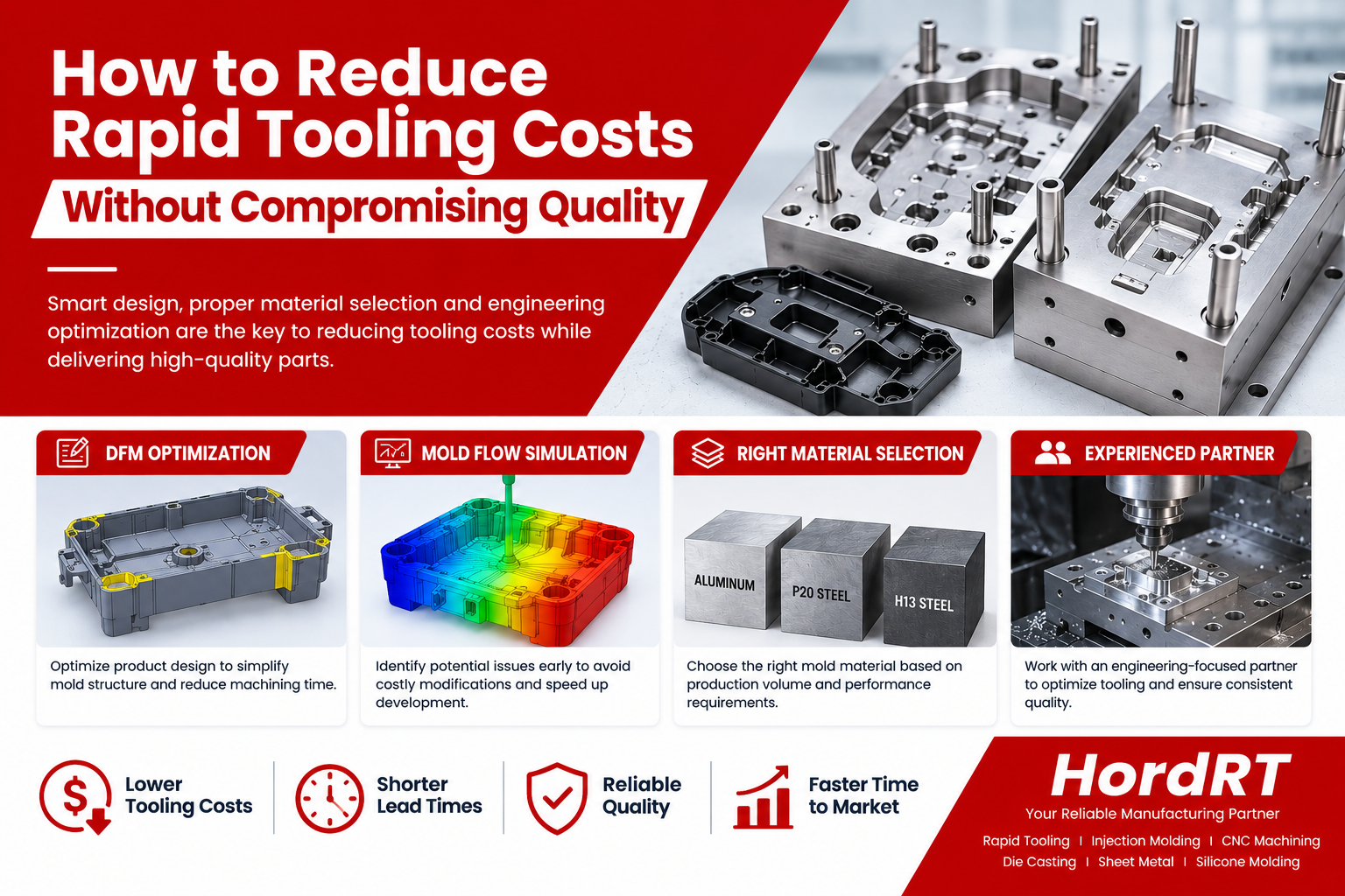
Skip to content
Blog details
Design Tips

Injection molding is an important manufacturing process, which is used in many industries.During the process, the injection molten material (resin) into the cavity of metal mold under high pressure. Once the materials cools down, the thimble ejects the finished part from the mold.
A manufacturability design can speed up production time and reduce production cost. With the experience of injection molding, we have collected a series of design tips aims at helping you improve the manufacturability of parts. Learn about the general wall thickness, draft, ribs and other design factors. These may improve the moldability of the parts, and reduce the chance of production hiccups, cosmetic defects and other issues.

1. General wall thickness

The most important design requirement for getting good molded parts: wall thickness should be kept uniform. If parts are too thick, it can lead to sink, warp, and inaccurate or non-functional parts.
Bebefits:
• Smooth flow of material
• Even cooling & Shrinkage
• Reduced risk of warpage
• Reduced mold in stresses

Decrease the maximum wall thickness of a part to shorten the cycle time (injection time and cooling time specifically) and reduce the part volume

INCORRECT

INCORRECT

CORRECT

CORRECT

2. Draft

When designing a part for plastic injection molding, it's critical to add the draft angle to the part's faces. Apply a draft angle of can help the parts release from a mold easily. Without draft angles, parts run the risk of poor cosmetic finishes, and may scratch, break, or warp due to molding stresses caused by the plastic cooling. However, the draft angle depends on the materials, wall thickness, shape and shrink rate of the parts.

INCORRECT - No draft angle

CORRECT- Add draft angle

3. Ribs

To prevent sink marks, the rib thickness should be btween 50%-60% of nominal wall thickness. And the height of rib should be about two and a half to three times nominal wall thickness.

Add ribs for structural support, rather than increasing the wall thickness.

INCORRECT

CORRECT

If the orient of ribs perpendicular to the axis may occur bending.

INCORRECT

CORRECT

4. Bosses

Bosses are defined as protruding studs on a part that assist in the assembling of a plastic partwith another part. They can used for pressed in assembly, self tapped screw assembly or tapped or a standard machine screw.

• Wall thickness of bosses should be no more than 60% of the main wall thickness.
• Radius at the base should be at least 25% of the main wall thickness
• Should be supported by ribs that connect to adjacent walls or by gussets at the base.

INCORRECT----Isolated boss

CORRECT----Isolated boss with ribs (left) or gussets (right)

If a boss must be placed near a corner, it should be isolated using ribs.

INCORRECT
Boss in corner

CORRECT
Ribbed boss in corner

5. Raddi

Sharp corners have high-stress concentration and plastic flow is hindered. Raddi reduce stress concentration in mold parts and provide a streamlined flow path for the molten plastic, resulting in an easier fill of the mold.
Radius should always be a consideration in regard to the part's thickness eliminating the likelihood of areas of high stress and possible breakage of the part
A general rule of thumb is that the thickness at a corner should be in the range of 0.9 times the nominal thickness to 1.2 the nominal thickness of thepart

INCORRECT

CORRECT

6. Undercuts

Undercuts are those features that prevent the injection-mold parts ejection from the mold without any structural damage. When design a part, the following tiems should be paid attention:

• Minimize the number of external undercuts
• External undercuts require side-cores which add to the tooling cost
• Some simple external undercuts can be molded by relocating the parting line

Simple external undercut

Mold cannot separate

New parting line allows undercut

Redesigning a feature can remove an external undercut

Part with hinge

Part with hinge

Hinge requires side-core

New hinge can be molded

• Minimize the number of internal undercuts
• Internal undercuts often require internal core lifters which add to the tooling cost
• Designing an opening in the side of a part can allow a side-core to form an internal undercut

If you have any new project,please feel free to contact us rfq@hordrt.com

Other Articles You Might Enjoy:
Ready to Work On your Next Project?

Let us help you provide high quality parts in short time. Get your project started now!

Get Quote
Get instant pricing, project lead times, and DFM feedback.
doc|docx|ppt|pptx|pdf|jpg|png|STEP|STP|STL|ZIP|RAR
IGES|IGS|SLDPRT|3DM|SAT or X_T files