Johnny Xiong
Rapid Tooling Expert
Contents
Injection molding is a mature, high-volume manufacturing process, but the real skill is using mold design to expand product functionality while keeping cost and cycle time under control. Side actions (sliders, side pulls, side cores) are among the most powerful mold features for achieving that balance: they let you create undercuts, side holes, ribs, snap-fits, threads, and other geometries that cannot be produced by a simple straight-pull two-plate mold. Used well, side actions let designers consolidate parts, improve strength, and reduce assembly — at the cost of increased tooling complexity that must be managed.
This article provides a deep, practical guide to using side actions for design optimization. It covers: what side actions are and why they matter; a detailed taxonomy (including a practical table you can use when choosing a solution); extended design-for-manufacturing considerations (geometry, tolerances, material, cooling, venting, parting line strategies); tooling and maintenance implications; cost-management techniques and case studies
1. Why Side Actions Matter
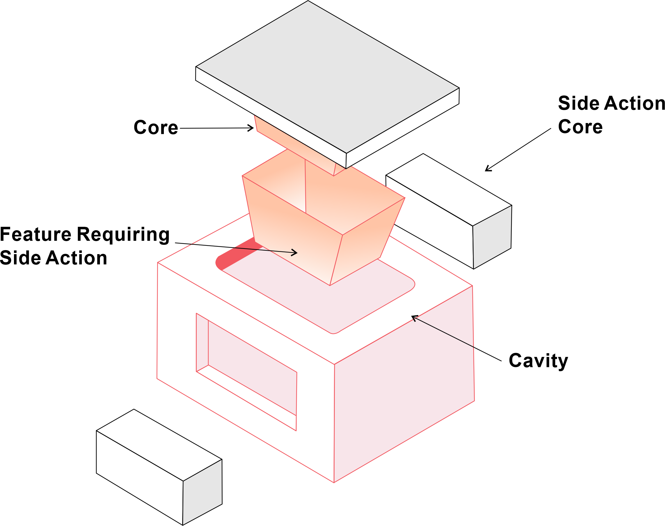
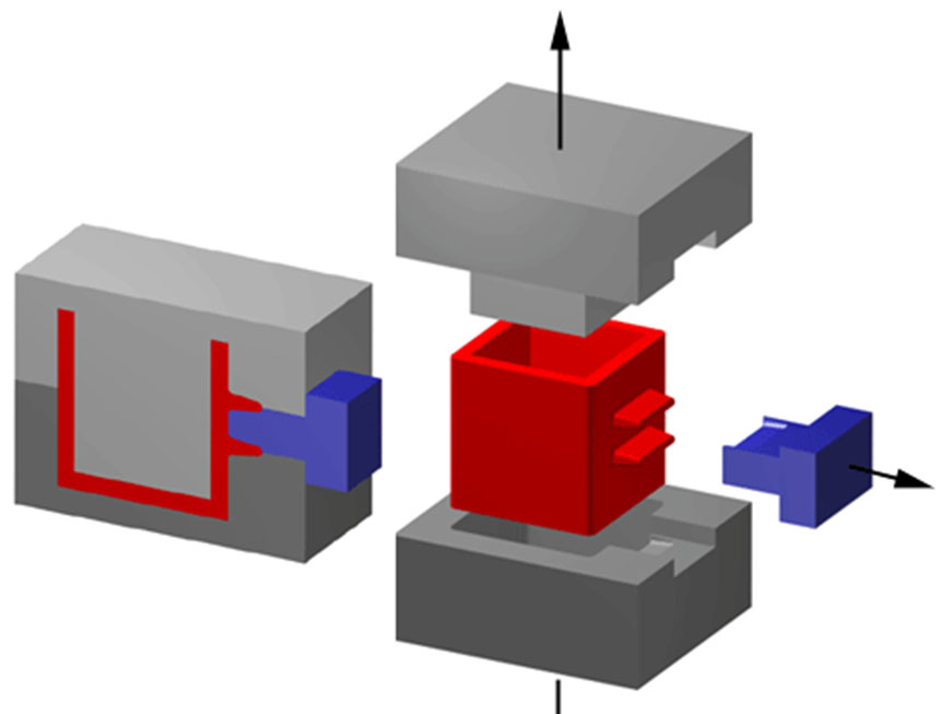
The immediate job of a side action is mechanical: move in and out to allow molding of features that would otherwise lock the part into the mold. But the design-level impact is much broader:
Functional consolidation. Side actions let you fold functions into a single molded component — latches, clips, snap hooks, cable ports, and sliding guides — which reduces parts count and downstream assembly.
Performance and durability. One-piece molded features (versus assembled ones) tend to be stronger, more repeatable, and less prone to failure from improper assembly or wear.
Precision and repeatability. Molded features driven by the tool geometry keep tolerances far better than most post-mold machining for long production runs.
Aesthetics and ergonomics. Side actions permit clean edge details, tight fillets, and flush openings that improve perceived quality.
Lifecycle cost reduction. Higher upfront mold cost can be offset by lower per-part cost, less rework, reduced inventory, and faster assembly lines.
2. Types of Side Actions
| Type | Movement | Typical Use Cases | Strengths | Limitations |
| Straight (Linear) Slider | Linear, perpendicular to parting line | Small side holes, tabs, thin snaps, external ribs | Simple, low cost, reliable | Limited stroke, potential flow interruption near slider |
| Angled Slider | Slider moves along an angled path | Features that need combined lateral + axial clearance | Access to angled undercuts, more geometry flexibility | More complex cams/guideways; alignment critical |
| Cam-Operated Slider | Mechanical cam actuates slider synchronized with mold opening | Multiple sliders needing sequential timing | Fully mechanical timing, no external actuation | Wear on cam, precise tuning required |
| Hydraulic / Pneumatic Slider | Powered by hydraulic cylinder or air | Heavy slides, deep undercuts, long stroke | High force, smooth travel, good for large inserts | Adds utilities (hydraulic/pneumatic systems), higher cost & maintenance |
| Lifter / Ejector Lifter | Vertical or inclined lifter (often tied to eject sequence) | Internal grooves, partial undercuts, small internal threads | Good for internal features, compact | Must be timed with ejection; limited travel |
| Collapsible Core | Core collapses inward to release internal threads / undercuts | Internal threads, hollow cylinders with internal ribs | Allows complex internal geometry | High tooling complexity, needs precision machining |
| Multi-axis / Compound Mechanisms | Combination of linear, angular and lifter motions | Parts with many conflicting undercuts and complex sequences | Maximum design freedom | Highest cost, most complex maintenance and sequencing |
3. Geometry & Design Guidelines
Designers must make deliberate choices to keep side-action costs reasonable while preserving function. The following are practical, field-proven guidelines.
3.1 Early engagement
Decide whether undercuts will be required during concept or early detailed design — late changes to add sliders are costly and delay schedules.
3.2 Minimize stroke and complexity
Design features to use the shortest possible slider travel. That reduces mechanism size and cost, lowers cycle time, and improves life.
3.3 Draft angles and surface finish
Even on side-pulled faces, provide draft — typically 0.5°–2° depending on material and surface texture. Higher gloss or textured finishes require slightly more draft.
3.4 Shutoff and sealing geometry
Where sliders meet stationary steel, the shutoff face should have an adequate angle and generous radii to avoid flashing. A shutoff angle of 3°–5° is a good rule of thumb; thin shutoffs increase wear.
3.5 Avoid very deep/continuous undercuts
If an undercut extends a long distance along the part, consider splitting the geometry or relocating features to parting lines. Multiple small sliders are often worse than a single well-placed one.
3.6 Positioning relative to flow and weld lines
Place sliders away from major flow fronts and areas where weld lines will form. A slider located at flow-front junctions increases the chance of knit-line weakness.
3.7 Ribs, fillets, and wall thickness near sliders
Maintain consistent wall thickness and generous fillets near slider transitions to avoid sink and stress concentration. If a slider creates a thin lip, evaluate stress during assembly/use.
3.8 Tolerances and fits
Tighter injection-molded tolerances near slider interfaces require careful mold design. Discuss target tolerances with the toolmaker — ±0.05 mm may be feasible for small features but is tool-dependent.
4. Material, Cooling, and Process Considerations
Choice of polymer, cooling pattern, and cycle sequence influence slider performance and mold life.
4.1 Material shrinkage and side-action clearance
Materials with higher shrinkage (e.g., some nylons) may reduce the effective clearance between slider and part. Account for expected shrinkage and holdback in clearance calculations.
4.2 Hygroscopic / engineering resins
For materials that absorb moisture, dimensional stability can shift; plan for pre-drying and tolerance windows accordingly.
4.3 Cooling layout around sliders
Sliders interrupt ideal cooling channels. Use conformal cooling where possible, or accept slightly longer cycles and add cooling channels in the mold steel away from the slider mechanisms.
4.4 Venting
Where a slider seals against the cavity, provide venting paths to avoid trapped air and burn marks. Slide-to-body interfaces often need micro-vents or escape paths.
4.5 Cycle sequence and synchronization
For cam- or hydraulic-driven slides, ensure synchronization with the machine and ejection sequence. Incorrect timing leads to jams, flash, or tool damage.
5. Tooling & Maintenance
Side actions add moving parts and wear points. Collaboration with the toolroom will avoid surprises.
5.1 Tolerance on mold steel
Matrices and sliders must be hardened and ground accurately. Inform the toolmaker of the critical dimensions and expected production volume so they can select appropriate steels and coatings.
5.2 Lubrication and guideways
Sliders require lubrication grooves, anti-friction coatings, or bushings. For high-cavity molds, consider linear bearings for long-life and low variation.
5.3 Wear and replaceable components
Design shutdowns to allow replacement of wear shoes, keys, and bushes without full tool disassembly. Modularization reduces downtime.
5.4 Corrosion protection and seals
Hydraulic systems require seals; in humid or corrosive environments, use stainless inserts or protective coatings at exposed slider surfaces.
5.5 Accessibility and safety
Place sliders and their access points where maintenance can be performed safely. Avoid burying cams or cylinders inside inaccessible regions.
6. Cost Management Strategies
Side actions increase upfront tooling cost. Here are targeted approaches to manage total cost of ownership.
6.1 Evaluate break-even volumes
Calculate the amortized mold cost per part versus the cost of post-mold operations (machining, assembly). Usually above a few thousand to tens of thousands of parts, sliders pay off.
6.2 Simplify motion
Prefer straight linear slides where possible. Only use angled or multi-axis mechanisms when necessary.
6.3 Consolidate features
Group undercuts that share a common slide whenever feasible — one multi-feature slider is cheaper than many small ones.
6.4 Minimize steel-to-steel engagement area
Shallow shutoffs and narrow engagement reduce steel wear and maintenance — but balance this with risk of flash.
6.5 Consider alternate parting strategies
Sometimes shifting the parting line or splitting the part differently eliminates the slider entirely; weigh that against assembly and cosmetic implications.
6.6 Use standardized components
Off-the-shelf hydraulic cylinders, cams, and bushings are cheaper and faster than fully custom mechanisms.
7. Case Studies
Case A — Handheld Medical Device (Precision Internal Rails)
Problem: Internal sliding rails and cable channels required ±0.1 mm alignment for consistent operation. Secondary machining was costly and introduced variability.
Solution: Designed lifter-type side actions for the rails and a collapsible core for a central cavity. Cooling channels were routed to avoid the slider area; cam-actuated sequencing synchronized rails with ejection.
Outcome: Final part tolerance improved, assembly time reduced by 80%, and scrap due to misalignment fell to near zero. Upfront mold cost increased ~25% but payback in two production runs.
Case B — Automotive Exterior Trim with Snap-Fits
Problem: Multiple side snaps and locking hooks would have required inserts or manual assembly.
Solution: Combined straight sliders to form exterior snaps and a couple of angled sliders for hooks. Steel insert pockets were machined into sliders to reduce wear.
Outcome: Zero fasteners, reduced assembly steps, improved in-field durability. Tool maintenance schedule included quick-change wear inserts.
Case C — Consumer Electronics Airflow and I/O Ports
Problem: Ports and vents needed to be clean, flush, and without visible seams.
Solution: Angled sliders created vent channels and port recesses. The injection gate and ribs were re-located to optimize flow and avoid weld lines.
Outcome: Premium aesthetics achieved, assembly eliminated for those modules, cycle time increased slightly due to additional cooling need — acceptable versus added value.
8. Common Problems and How to Avoid Them
Flash at slider interfaces — increase shutoff precision, add micro-vents, or slightly increase shutoff angle.
Slider jamming — ensure adequate lubrication, proper guideways, and avoid contamination build-up.
Weld / knit line weakness near sliders — revise gate location or add injection gates to balance flow.
Excessive wear — use hardened wear plates, replaceable inserts, or surface coatings.
Poor ejection timing — verify cam profiles and hydraulic timing in slow-motion dry runs.
Conclusion
Side actions are not just a “mold trick” — they are a deliberate design lever. When used thoughtfully, they unlock functionality, reduce assembly, and elevate product quality. The trade-off is added mold complexity, which demands close collaboration between designers and toolmakers, careful material and cooling planning, and a focus on maintainability.
Use the taxonomy and guidelines in this article to pick the simplest effective side-action type, design with minimal stroke and clearances, and validate with simulation early. If you manage those trade-offs actively, side actions can shift the balance from “tooling burden” to “competitive product advantage.”
About HordRT
With over 10 years of experience in precision injection molding and tooling engineering, HordRT specializes in mold design, side-action mechanisms, multi-cavity tooling, and high-quality plastic part production. We support clients from concept development to mass manufacturing, providing DFM analysis, mold flow simulation, rapid prototyping, and stable large-scale production. Our in-house tooling center and automated injection facilities ensure consistent quality, competitive lead times, and optimized total manufacturing cost.
We welcome global customers seeking reliable engineering support and long-term production partnerships. Contact us now!