Contents
Pressure die casting is a versatile and efficient manufacturing process, ideal for producing complex metal components in large quantities with high precision and smooth finishes. However, to take full advantage of this process, thoughtful design considerations must be incorporated to ensure both manufacturability and the desired part performance.
This article outlines key factors that engineers and designers should keep in mind when designing parts for pressure die casting.
1. Material Selection
One of the first decisions in the design process is selecting the right material. Commonly used metals in pressure die casting include aluminum, magnesium, and zinc alloys. Each material has different characteristics such as strength, weight, corrosion resistance, and thermal conductivity. For example:
- Aluminum: Known for its lightweight and high strength-to-weight ratio, aluminum is excellent for automotive and aerospace applications. However, it may experience more shrinkage during cooling.
- Magnesium: Lighter than aluminum, magnesium is suitable for parts that require a high strength-to-weight ratio, especially in the electronics and automotive industries.
- Zinc: Zinc alloys are often used for smaller parts due to their excellent fluidity and low melting point, making them ideal for intricate designs.
Understanding the material's properties and its interaction with the die-casting process is essential in ensuring the final part meets functional and performance requirements.
2. Wall Thickness
Wall thickness plays a crucial role in pressure die casting design. It directly affects both the production cost and the performance of the part. Maintaining uniform wall thickness is critical for:
- Cooling Consistency: Inconsistent wall thickness can lead to uneven cooling, causing defects such as warping, porosity, or shrinkage. Thicker sections will cool more slowly, potentially leading to internal stresses.
- Flow of Molten Metal: Uniform thickness helps the molten metal flow more evenly through the die, reducing the chances of air entrapment or incomplete filling.
- Cost Efficiency: Thicker walls require more material, increasing both the weight and material cost. Additionally, more time is needed for cooling, which can extend production cycles.
The recommended wall thickness generally depends on the material being used, but in most cases, thin walls (between 1-4mm) are preferred to balance strength and efficiency.
3. Draft Angle
In pressure die casting, incorporating draft angles into the design is essential for easy removal of the part from the die. A draft is a taper applied to the vertical faces of the part, which allows it to release smoothly without damaging the casting or the die.
Key considerations for draft angles include:
- Die life: Adequate draft angles reduce the friction between the part and the die, extending the life of the die.
- Material Type: Different materials require varying draft angles. For example, aluminum casting generally requires a draft of 1 to 3 degrees, whereas softer metals like zinc may allow for smaller drafts.
- Complexity of the Design: Intricate designs or deep sections often require draft angles to ensure the part can be easily removed without deforming or getting stuck in the die.
Typically, designers aim for a draft angle of at least 1-2 degrees for internal surfaces and 2-3 degrees for external surfaces, but these values may vary depending on the specific geometry and material..
4. Fillets and Radii
Sharp corners and edges should be avoided in pressure die casting designs. Instead, fillets (rounded internal corners) and radii (rounded external corners) should be used to reduce stress concentration points and enhance the overall flow of molten metal into the die.
- Improved Metal Flow: Rounded corners allow for smoother molten metal flow, reducing the likelihood of air entrapment and incomplete filling.
- Stress Distribution: Sharp corners tend to concentrate stress, leading to potential failure points in the final part. By using fillets and radii, stress is distributed more evenly, improving the part's strength and durability.
- Easier Ejection: Fillets and radii also facilitate easier ejection of the part from the die, reducing the risk of damage to both the part and the tooling.
A typical fillet radius is about 0.5 to 3mm, but this can vary based on the specific design and material.
5. Ribbing and Bosses
Ribs and bosses are essential design elements that can be used to increase the strength and rigidity of cast parts without adding excessive material.
- Ribs: Ribs are thin walls added to areas requiring additional support. They improve stiffness and reduce the risk of warping without significantly increasing the overall weight or material cost. The thickness of the ribs should be approximately 50-70% of the main wall thickness to avoid hot spots and ensure uniform cooling.
- Bosses: Bosses are cylindrical features often used to create mounting points or threaded holes. These should be designed with fillets at the base to avoid stress concentration and to ensure proper metal flow around the feature. Bosses should also be hollow where possible to minimize material usage and prevent sink marks during cooling.
Ribs and bosses should be strategically placed to maintain the strength-to-weight ratio, ensuring the part meets structural requirements without adding unnecessary weight.
6. Gate Placement and Venting
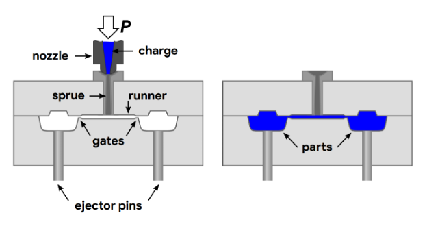
Gate placement refers to where the molten metal enters the die cavity. Proper placement of gates is crucial for:
- Minimizing Defects: Incorrect gate placement can cause turbulence, air entrapment, or uneven filling, leading to casting defects like porosity or cold shuts.
- Efficient Metal Flow: Gates should be placed to ensure the molten metal flows smoothly and fills the die completely before cooling starts.
In addition to gate placement, proper venting is also necessary to allow trapped air to escape during casting. Poor venting can result in air pockets, which compromise the part's structural integrity. Vents should be designed to let air out without allowing molten metal to escape, ensuring a clean, defect-free casting.
7. Tolerances and Shrinkage Allowances
Pressure die casting offers excellent dimensional accuracy, but designers still need to account for tolerances and shrinkage. Metal contracts as it cools, so shrinkage allowance must be built into the design to ensure the final part matches the desired dimensions. The amount of shrinkage depends on the material, with some metals like aluminum and magnesium having higher shrinkage rates than others.
- Tolerances: Tight tolerances may increase production costs, so designers should only specify critical tolerances where absolutely necessary.
- Shrinkage: Shrinkage can vary between 0.5% to 1.5%, depending on the material and part geometry. Design adjustments should be made accordingly to achieve the required final dimensions.
8. Surface Finish and Post-Processing
The surface finish of pressure die-cast parts is generally smooth and suitable for many applications straight out of the mold. However, some designs may require additional finishing processes, such as machining, painting, or anodizing. Designers should consider how post-processing steps will affect the final part and ensure that adequate material is left for any secondary operations.
- Machining Allowances: If post-casting machining is needed, additional material should be left on the surfaces to be machined.
- Surface Treatments: If surface treatments like plating or powder coating are required, the design should account for the added thickness from these processes.
Conclusion
Designing for pressure die casting involves a careful balance between manufacturability, material properties, and part performance. By considering factors such as material selection, wall thickness, draft angles, and proper gating, engineers can ensure the efficient production of high-quality components that meet their intended applications. Thoughtful design can lead to reduced production costs, improved die life, and better-performing parts.
Whether you're designing automotive components, electronic housings, or industrial parts, keeping these design considerations in mind will help optimize the pressure diegcasting process and ensure the success of your project!
-q4gvl4k29y4hq8j9rjpapvj0ft06fje63olt7p210i.png)
